2019 DODGE CHALLENGER SRT lock
[x] Cancel search: lockPage 53 of 500
WARNING!(Continued)
•Only ride in available seating positions equipped
with seat belt systems. Always properly wear your
seat belt. Failure to do so could result in an increased
risk of serious injury or death in the event of an
accident.
• Be sure everyone in your vehicle is in a seat and
using a seat belt properly. Occupants, including the
driver, should always wear their seat belts whether
or not an air bag is also provided at their seating
positions to minimize the risk of severe injury or
death in the event of a crash.
• All occupants, including the driver, should not oper-
ate a vehicle or sit in a vehicle’s seat if the head
restraints are not in place of their proper positions in
order to minimize the risk of neck injury in the event
of a crash.
• Head restraints should never be adjusted while the
vehicle is in motion. Driving a vehicle with the head
restraints improperly adjusted or removed could
cause serious injury or death in the event of a
collision.
Passenger Seat Easy Entry
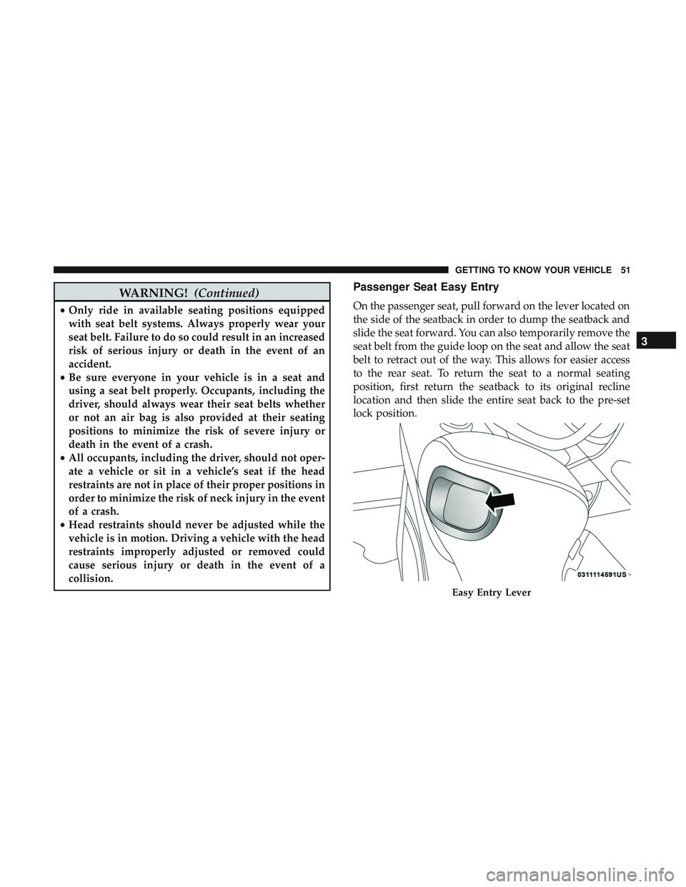
On the passenger seat, pull forward on the lever located on
the side of the seatback in order to dump the seatback and
slide the seat forward. You can also temporarily remove the
seat belt from the guide loop on the seat and allow the seat
belt to retract out of the way. This allows for easier access
to the rear seat. To return the seat to a normal seating
position, first return the seatback to its original recline
location and then slide the entire seat back to the pre-set
lock position.
Easy Entry Lever
3
GETTING TO KNOW YOUR VEHICLE 51
Page 54 of 500
NOTE:
•The front passenger seat needs to slide back to the
“remembered” pre-set position for the fore-aft adjuster
to be properly locked. For example, if the front passen-
ger has the seat adjusted full rear and exits the vehicle to
let a rear passenger enter using the easy entry handle,
the fore-aft adjuster needs to slide back to the full rear
position. If the adjuster is not returned to the original
pre-set position, the seat will appear to be loose.
• Also, if the front passenger uses the easy entry handle
and then lifts up the recliner handle without moving the
seat back to its original pre-set position, the recliner will
not lock until it is moved to the full recline position.
HEAD RESTRAINTS
Head restraints are designed to reduce the risk of injury by
restricting head movement in the event of a rear-impact.
Head restraints should be adjusted so that the top of the
head restraint is located above the top of your ear.
WARNING!
•All occupants, including the driver, should not oper-
ate a vehicle or sit in a vehicle’s seat until the head
restraints are placed in their proper positions in
order to minimize the risk of neck injury in the event
of a crash.
• Head restraints should never be adjusted while the
vehicle is in motion. Driving a vehicle with the head
restraints improperly adjusted or removed could
cause serious injury or death in the event of a
collision.
NOTE: Do not reverse the head restraints (making the rear
of the head restraint face forward) in an attempt to gain
additional clearance to the back of your head.
Reactive Head Restraints — Front Seats
The front driver and passenger seats are equipped with
Reactive Head Restraints (RHR). In the event of a rear
impact, the RHRs will automatically extend forward mini-
mizing the gap between the back of the occupants head
and the RHR.
52 GETTING TO KNOW YOUR VEHICLE
Page 57 of 500

WARNING!(Continued)
•All occupants, including the driver, should not oper-
ate a vehicle or sit in a vehicle’s seat if the head
restraints are not in place of their proper positions in
order to minimize the risk of neck injury in the event
of a crash.
• Head restraints should never be adjusted while the
vehicle is in motion. Driving a vehicle with the head
restraints improperly adjusted or removed could
cause serious injury or death in the event of a
collision.
STEERING WHEEL
Manual Tilt/Telescoping Steering Column — If
Equipped
This feature allows you to tilt the steering column upward
or downward. It also allows you to lengthen or shorten the
steering column. The tilt/telescoping lever is located below
the steering wheel at the end of the steering column. To unlock the steering column, pull the lever downward.
To tilt the steering column, move the steering wheel
upward or downward as desired. To lengthen or shorten
the steering column, pull the steering wheel outward or
push it inward as desired. To lock the steering column in
position, push the lever upward until fully engaged.
Manual Tilt/Telescoping Control Handle
3
GETTING TO KNOW YOUR VEHICLE 55
Page 58 of 500

WARNING!
Do not adjust the steering column while driving.
Adjusting the steering column while driving or driv-
ing with the steering column unlocked, could cause the
driver to lose control of the vehicle. Failure to follow
this warning may result in serious injury or death.
Power Tilt/Telescoping Steering Column — If
Equipped
This feature allows you to tilt the steering column upward
or downward. It also allows you to lengthen or shorten the
steering column. The power tilt/telescoping steering col-
umn switch is located below the multifunction switch on
the steering column.To tilt the steering column, move the switch up or down as
desired. To lengthen or shorten the steering column, pull
the switch toward you or push the switch away from you
as desired.
WARNING!
Do not adjust the steering column while driving.
Adjusting the steering column while driving or driv-
ing with the steering column unlocked, could cause the
driver to lose control of the vehicle. Failure to follow
this warning may result in serious injury or death.
Power Tilt/Telescoping Switch
56 GETTING TO KNOW YOUR VEHICLE
Page 63 of 500
EXTERIOR LIGHTS
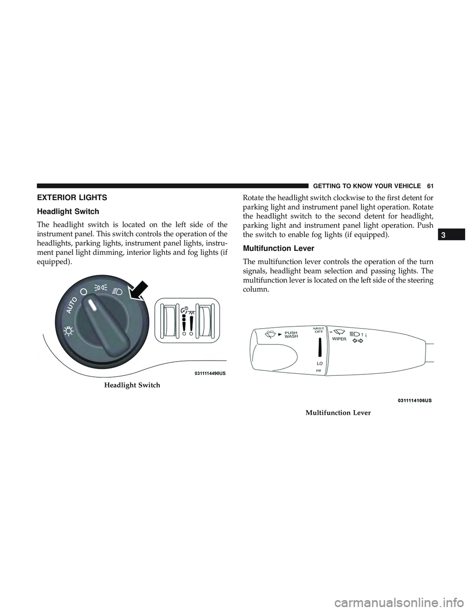
Headlight Switch
The headlight switch is located on the left side of the
instrument panel. This switch controls the operation of the
headlights, parking lights, instrument panel lights, instru-
ment panel light dimming, interior lights and fog lights (if
equipped).Rotate the headlight switch clockwise to the first detent for
parking light and instrument panel light operation. Rotate
the headlight switch to the second detent for headlight,
parking light and instrument panel light operation. Push
the switch to enable fog lights (if equipped).
Multifunction Lever
The multifunction lever controls the operation of the turn
signals, headlight beam selection and passing lights. The
multifunction lever is located on the left side of the steering
column.
Headlight Switch
Multifunction Lever
3
GETTING TO KNOW YOUR VEHICLE 61
Page 65 of 500
Automatic Headlights
This system automatically turns the headlights on or off
according to ambient light levels. To turn the system on,
rotate the headlight switch counterclockwise to the AUTO
position. When the system is on, the headlight time delay
feature is also on. This means the headlights will stay on
for up to 90 seconds after you place the ignition into the
OFF position. The headlight time delay can be pro-
grammed 0/30/60/90 seconds.
Refer to “Uconnect Settings” in “Multimedia” for further
information.
To turn the automatic system off, move the headlight
switch out of the AUTO position.
NOTE:The engine must be running before the headlights
will come on in the automatic mode.
Parking Lights
Turn the headlight switch knob to the first detent to turn
the parking lights on. This also turns on all instrument
panel lighting.
Headlights On With Wipers
When this feature is active, the headlights will turn on after
the wipers are turned on if the headlight switch is placed in the AUTO position and programmable feature is set to on.
In addition, the headlights will turn off when the wipers
are turned off if they were turned on by this feature.
NOTE:
The “Headlights On With Wipers” feature can be
turned on or off using the Uconnect System. Refer to
“Uconnect Settings” in “Multimedia” for further informa-
tion.
Headlight Time Delay
This feature provides the safety of headlight illumination
for up to 90 seconds when leaving your vehicle in an unlit
area with the headlight switch in the O (off) position.
To activate the delay feature, turn OFF the ignition switch
while the headlights are still on. Then, turn off the head-
lights within 45 seconds. The delay interval begins when
the headlight switch is turned off.
NOTE: The lights must be turned off within 45 seconds of
turning the ignition OFF to activate this feature.
If you turn the headlights, park lights or ignition switch
ON again, the system will cancel the delay.
If you turn the headlights off before the ignition, they will
turn off in the normal manner.
3
GETTING TO KNOW YOUR VEHICLE 63
Page 67 of 500

Lane Change Assist — If Equipped
Tap the multifunction lever up or down once, without
moving beyond the detent, and the turn signal (right or
left) will flash three times then automatically turn off.
INTERIOR LIGHTS
The interior lights come on when a door is opened.
To protect the battery, the interior lights will turn off
automatically ten minutes after the ignition is moved to the
OFF position. This will occur if the interior lights were
switched on manually or are on because a door is open.
The Battery Protection also includes the glove compart-
ment light and the trunk light. To restore interior light
operation after automatic battery protection is enabled
(lights off), either place the ignition in the ON/RUN
position or cycle the light switch.
Map/Reading Lights
These lights are mounted between the sun visors on the
overhead console. Each light is turned on by pushing the
lens. Push the lens a second time to turn off the light. These
lights also turn on when a door is opened, when the unlock
button on the remote keyless entry key fob is pushed, or
when the dimmer control is turned fully upward, past the
second detent.
Overhead Console
3
GETTING TO KNOW YOUR VEHICLE 65
Page 75 of 500
IconDescription
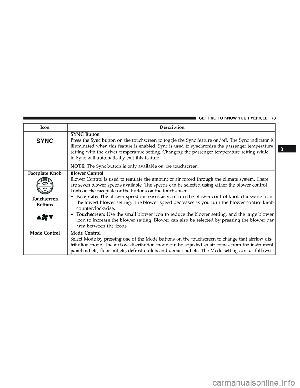
SYNC Button
Press the Sync button on the touchscreen to toggle the Sync feature on/off. The Sync indicator is
illuminated when this feature is enabled. Sync is used to synchronize the passenger temperature
setting with the driver temperature setting. Changing the passenger temperature setting while
in Sync will automatically exit this feature.
NOTE:The Sync button is only available on the touchscreen.
Faceplate Knob
Touchscreen Buttons
Blower Control
Blower Control is used to regulate the amount of air forced through the climate system. There
are seven blower speeds available. The speeds can be selected using either the blower control
knob on the faceplate or the buttons on the touchscreen.
• Faceplate: The blower speed increases as you turn the blower control knob clockwise from
the lowest blower setting. The blower speed decreases as you turn the blower control knob
counterclockwise.
• Touchscreen: Use the small blower icon to reduce the blower setting, and the large blower
icon to increase the blower setting. Blower can also be selected by pressing the blower bar
area between the icons.
Mode Control Mode Control Select Mode by pressing one of the Mode buttons on the touchscreen to change that airflow dis-
tribution mode. The airflow distribution mode can be adjusted so air comes from the instrument
panel outlets, floor outlets, defrost outlets and demist outlets. The Mode settings are as follows:
3
GETTING TO KNOW YOUR VEHICLE 73