2019 DODGE CHALLENGER SRT towing
[x] Cancel search: towingPage 106 of 500

Instrument Cluster Descriptions
1. Tachometer•Indicates the engine speed in revolutions per minute
(RPM x 1000).
2. Instrument Cluster Display •When the appropriate conditions exist, this display
shows the instrument cluster display messages. Refer
to “Instrument Cluster Display” in “Getting To Know
Your Instrument Panel” for further information.
3. Speedometer •Indicates vehicle speed.
4. Fuel Gauge •The pointer shows the level of fuel in the fuel tank
when the Keyless Push Button Ignition is in the
ON/RUN position.
•
The fuel pump symbol points to the side of the
vehicle where the fuel door is located.
5. Temperature Gauge
•The temperature gauge shows engine coolant tem-
perature. Any reading within the normal range indi-
cates that the engine cooling system is operating
satisfactorily. •
The gauge pointer will likely indicate a higher tem-
perature when driving in hot weather, up mountain
grades, or when towing a trailer. It should not be
allowed to exceed the upper limits of the normal
operating range.
WARNING!
A hot engine cooling system is dangerous. You or
others could be badly burned by steam or boiling
coolant. You may want to call an authorized dealer for
service if your vehicle overheats. If you decide to look
under the hood yourself, see “Servicing And Mainte-
nance.” Follow the warnings under the Cooling System
Pressure Cap paragraph.
CAUTION!
Driving with a hot engine cooling system could dam-
age your vehicle. If the temperature gauge reads “H,”
pull over and stop the vehicle. Idle the vehicle with the
air conditioner turned off until the pointer drops back
into the normal range. If the pointer remains on the
“H,” turn the engine off immediately and call an
authorized dealer for service.
104 GETTING TO KNOW YOUR INSTRUMENT PANEL
Page 118 of 500

NOTE:
•The charging system is independent from load reduc-
tion. The charging system performs a diagnostic on the
charging system continuously.
• If the Battery Charge Warning Light is on it may indicate
a problem with the charging system. Refer to “Battery
Charge Warning Light” in “Getting To Know Your
Instrument Panel” for further information.
The electrical loads that may be switched off (if equipped),
and vehicle functions which can be affected by load
reduction:
• Heated Seat/Vented Seats/Heated Wheel
• Heated/Cooled Cup Holders — If Equipped
• Rear Defroster And Heated Mirrors
• HVAC System
• 115V AC Power Inverter System
• Audio and Telematics System
Loss of the battery charge may indicate one or more of the
following conditions: •
The charging system cannot deliver enough electrical
power to the vehicle system because the electrical loads
are larger than the capability of the charging system. The
charging system is still functioning properly.
• Turning on all possible vehicle electrical loads (e.g.
HVAC to max settings, exterior and interior lights,
overloaded power outlets +12V, 115V AC, USB ports)
during certain driving conditions (city driving, towing,
frequent stopping).
• Installing options like additional lights, upfitter electri-
cal accessories, audio systems, alarms and similar de-
vices.
• Unusual driving cycles (short trips separated by long
parking periods).
• The vehicle was parked for an extended period of time
(weeks, months).
• The battery was recently replaced and was not charged
completely.
• The battery was discharged by an electrical load left on
when the vehicle was parked.
116 GETTING TO KNOW YOUR INSTRUMENT PANEL
Page 122 of 500

— Battery Charge Warning Light
This warning light will illuminate when the battery is not
charging properly. If it stays on while the engine is run-
ning, there may be a malfunction with the charging system.
Contact an authorized dealer as soon as possible.
This indicates a possible problem with the electrical system
or a related component.
— Oil Pressure Warning Light
This warning light will illuminate to indicate low engine
oil pressure. If the light turns on while driving, stop the
vehicle, shut off the engine as soon as possible, and contact
an authorized dealer. A chime will sound when this light
turns on.
Do not operate the vehicle until the cause is corrected. This
light does not indicate how much oil is in the engine. The
engine oil level must be checked under the hood.
— Oil Temperature Warning Light
This warning light will illuminate to indicate the engine oil
temperature is high. If the light turns on while driving,
stop the vehicle and shut off the engine as soon as possible.
Wait for oil temperature to return to normal levels.
— Electronic Throttle Control (ETC) Warning
Light
This warning light will illuminate to indicate a problem
with the Electronic Throttle Control (ETC) system. If a
problem is detected while the vehicle is running, the light
will either stay on or flash depending on the nature of the
problem. Cycle the ignition when the vehicle is safely and
completely stopped and the transmission is placed in the
PARK position. The light should turn off. If the light
remains on with the vehicle running, your vehicle will
usually be drivable; however, see an authorized dealer for
service as soon as possible.
NOTE: This light may turn on if the accelerator and brake
pedals are pressed at the same time.
If the light continues to flash when the vehicle is running,
immediate service is required and you may experience
reduced performance, an elevated/rough idle, or engine
stall and your vehicle may require towing. The light will
come on when the ignition is placed in the ON/RUN or
ACC/ON/RUN position and remain on briefly as a bulb
check. If the light does not come on during starting, have
the system checked by an authorized dealer.
120 GETTING TO KNOW YOUR INSTRUMENT PANEL
Page 123 of 500
— Transmission Temperature Warning Light — If
Equipped
This warning light will illuminate to warn of a high
transmission fluid temperature. This may occur with
strenuous usage such as trailer towing. If this light turns
on, stop the vehicle and run the engine at idle or slightly
faster, with the transmission in PARK or NEUTRAL, until
the light turns off. Once the light turns off, you may
continue to drive normally.
WARNING!
If you continue operating the vehicle when the Trans-
mission Temperature Warning Light is illuminated you
could cause the fluid to boil over, come in contact with
hot engine or exhaust components and cause a fire.
CAUTION!
Continuous driving with the Transmission Tempera-
ture Warning Light illuminated will eventually cause
severe transmission damage or transmission failure.
— Electric Power Steering Fault Warning Light
This warning light will turn on when there’s a fault with
the EPS (Electric Power Steering) system. Refer to “Power
Steering” in “Starting And Operating” for further informa-
tion.
WARNING!
Continued operation with reduced assist could pose a
safety risk to yourself and others. Service should be
obtained as soon as possible.
— Door Open Warning Light
This indicator will illuminate when a door is ajar/open and
not fully closed.
NOTE: If the vehicle is moving, there will also be a single
chime.
— Trunk Open Warning Light
This indicator will illuminate when the trunk is open and
not fully closed.
NOTE: If the vehicle is moving, there will also be a single
chime.
4
GETTING TO KNOW YOUR INSTRUMENT PANEL 121
Page 124 of 500
Yellow Warning Lights
— Engine Check/Malfunction Indicator Warning
Light (MIL)
The Engine Check/Malfunction Indicator Light (MIL) is a
part of an Onboard Diagnostic System called OBD II that
monitors engine and automatic transmission control sys-
tems. This warning light will illuminate when the ignition
is in the ON/RUN position before engine start. If the bulb
does not come on when turning the ignition switch from
OFF to ON/RUN, have the condition checked promptly.
Certain conditions, such as a loose or missing gas cap, poor
quality fuel, etc., may illuminate the light after engine start.
The vehicle should be serviced if the light stays on through
several typical driving styles. In most situations, the ve-
hicle will drive normally and will not require towing.
When the engine is running, the MIL may flash to alert
serious conditions that could lead to immediate loss of
power or severe catalytic converter damage. The vehicle
should be serviced by an authorized dealer as soon as
possible if this occurs.
WARNING!
A malfunctioning catalytic converter, as referenced
above, can reach higher temperatures than in normal
operating conditions. This can cause a fire if you drive
slowly or park over flammable substances such as dry
plants, wood, cardboard, etc. This could result in death
or serious injury to the driver, occupants or others.
CAUTION!
Prolonged driving with the Malfunction Indicator
Light (MIL) on could cause damage to the vehicle
control system. It also could affect fuel economy and
driveability. If the MIL is flashing, severe catalytic
converter damage and power loss will soon occur.
Immediate service is required.
122 GETTING TO KNOW YOUR INSTRUMENT PANEL
Page 131 of 500
If any of these systems require service, the OBD II system
will turn on the Malfunction Indicator Light (MIL). It will
also store diagnostic codes and other information to assist
your service technician in making repairs. Although your
vehicle will usually be drivable and not need towing, see
an authorized dealer for service as soon as possible.
CAUTION!
•Prolonged driving with the MIL on could cause
further damage to the emission control system. It
could also affect fuel economy and driveability. The
vehicle must be serviced before any emissions tests
can be performed.
• If the MIL is flashing while the vehicle is running,
severe catalytic converter damage and power loss
will soon occur. Immediate service is required.
Onboard Diagnostic System (OBD II) Cybersecurity
Your vehicle is required to have an Onboard Diagnostic
system (OBD II) and a connection port to allow access to
information related to the performance of your emissions
controls. Authorized service technicians may need to ac-
cess this information to assist with the diagnosis and
service of your vehicle and emissions system.
WARNING!
• ONLY an authorized service technician should con-
nect equipment to the OBD II connection port in
order to read the VIN, diagnose, or service your
vehicle.
• If unauthorized equipment is connected to the OBD
II connection port, such as a driver-behavior tracking
device, it may:
• Be possible that vehicle systems, including safety
related systems, could be impaired or a loss of
vehicle control could occur that may result in an
accident involving serious injury or death.
• Access, or allow others to access, information
stored in your vehicle systems, including personal
information.
For further information, refer to “Cybersecurity” in “Mul-
timedia”.
4
GETTING TO KNOW YOUR INSTRUMENT PANEL 129
Page 144 of 500
Towing With HSA
HSA will also provide assistance to mitigate roll back while
towing a trailer.
WARNING!
•If you use a trailer brake controller with your trailer,
the trailer brakes may be activated and deactivated
with the brake switch. If so, there may not be enough
brake pressure to hold both the vehicle and the
trailer on a hill when the brake pedal is released. In
order to avoid rolling down an incline while resum-
ing acceleration, manually activate the trailer brake
or apply more vehicle brake pressure prior to releas-
ing the brake pedal.
• HSA is not a parking brake. Always apply the
parking brake fully when exiting your vehicle. Also,
be certain to place the transmission in PARK.
• Failure to follow these warnings can result in a
collision or serious personal injury.
Disabling And Enabling HSA
This feature can be turned on or turned off. To change the
current setting, proceed as follows: •
If disabling HSA using your instrument cluster display,
refer to “Instrument Cluster Display” in “Getting To
Know Your Instrument Panel” for further information.
• If disabling HSA using Uconnect Settings, refer to
“Uconnect Settings” in “Multimedia” for further infor-
mation.
For vehicles not equipped with an instrument cluster
display, perform the following steps:
1. Center the steering wheel (front wheels pointing straight forward).
2. Shift the transmission into PARK.
3. Apply the parking brake.
4. Start the engine.
5. Rotate the steering wheel slightly more than one-half turn to the left.
6. Push the “ESC Off” button located in the lower switch bank below the climate control four times within 20
seconds. The “ESC Off Indicator Light” should turn on
and turn off two times.
7. Rotate the steering wheel back to center and then an additional slightly more than one-half turn to the right.
142 SAFETY
Page 147 of 500
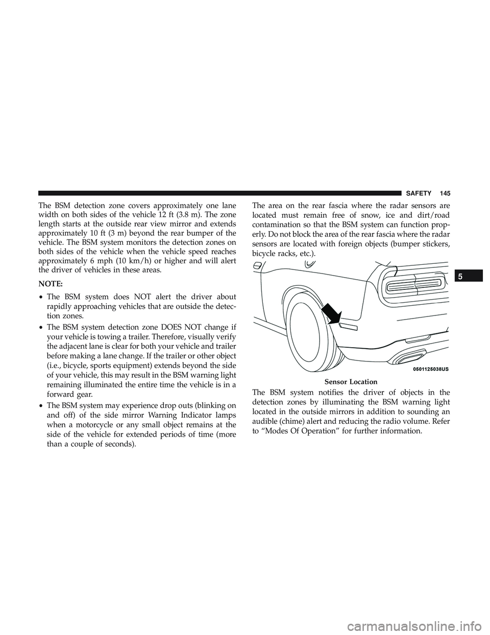
The BSM detection zone covers approximately one lane
width on both sides of the vehicle 12 ft (3.8 m). The zone
length starts at the outside rear view mirror and extends
approximately 10 ft (3 m) beyond the rear bumper of the
vehicle. The BSM system monitors the detection zones on
both sides of the vehicle when the vehicle speed reaches
approximately 6 mph (10 km/h) or higher and will alert
the driver of vehicles in these areas.
NOTE:
•The BSM system does NOT alert the driver about
rapidly approaching vehicles that are outside the detec-
tion zones.
• The BSM system detection zone DOES NOT change if
your vehicle is towing a trailer. Therefore, visually verify
the adjacent lane is clear for both your vehicle and trailer
before making a lane change. If the trailer or other object
(i.e., bicycle, sports equipment) extends beyond the side
of your vehicle, this may result in the BSM warning light
remaining illuminated the entire time the vehicle is in a
forward gear.
• The BSM system may experience drop outs (blinking on
and off) of the side mirror Warning Indicator lamps
when a motorcycle or any small object remains at the
side of the vehicle for extended periods of time (more
than a couple of seconds). The area on the rear fascia where the radar sensors are
located must remain free of snow, ice and dirt/road
contamination so that the BSM system can function prop-
erly. Do not block the area of the rear fascia where the radar
sensors are located with foreign objects (bumper stickers,
bicycle racks, etc.).
The BSM system notifies the driver of objects in the
detection zones by illuminating the BSM warning light
located in the outside mirrors in addition to sounding an
audible (chime) alert and reducing the radio volume. Refer
to “Modes Of Operation” for further information.
Sensor Location
5
SAFETY 145