2019 DODGE CHALLENGER SRT cooling
[x] Cancel search: coolingPage 77 of 500
Climate Control Functions
A/C (Air Conditioning)
The Air Conditioning (A/C) button allows the operator to
manually activate or deactivate the air conditioning sys-
tem. When the air conditioning system is turned on, cool
dehumidified air will flow through the outlets into the
cabin. For improved fuel economy, press the A/C button to
turn off the air conditioning and manually adjust the
blower and airflow mode settings. Also, make sure to select
only Panel, Bi-Level, or Floor modes.
NOTE:
•For Manual Climate Controls, if the system is in Mix,
Floor or Defrost Mode, the A/C can be turned off, but
the A/C system shall remain active to prevent fogging of
the windows.
• If fog or mist appears on the windshield or side glass,
select Defrost mode, and increase blower speed if
needed.
• If your air conditioning performance seems lower than
expected, check the front of the A/C condenser (located
in front of the radiator), for an accumulation of dirt or
insects. Clean with a gentle water spray from the front of
the radiator and through the condenser. MAX A/C
MAX A/C sets the control for maximum cooling perfor-
mance.
Press and release to toggle between MAX A/C and the
prior settings. The button illuminates when MAX A/C is
on.
In MAX A/C, the blower level and mode position can be
adjusted to desired user settings. Pressing other settings
will cause the MAX A/C operation to switch to the selected
setting and MAX A/C to exit.
Recirculation
In cold weather, use of Recirculation mode may lead to
excessive window fogging. The Recirculation feature may
be unavailable (button on the touchscreen greyed out) if
conditions exist that could create fogging on the inside of
the windshield.
Automatic Temperature Control (ATC)
Automatic Operation
1. Push the AUTO button on the faceplate, or the AUTO
button on the touchscreen on the Automatic Tempera-
ture Control (ATC) Panel.
3
GETTING TO KNOW YOUR VEHICLE 75
Page 78 of 500
2. Next, adjust the temperature that you would like thesystem to maintain by adjusting the driver and passen-
ger temperature control buttons. Once the desired tem-
perature is displayed, the system will achieve and
automatically maintain that comfort level.
3. When the system is set up for your comfort level, it is not necessary to change the settings. You will experience
the greatest efficiency by simply allowing the system to
function automatically.
NOTE:
• It is not necessary to move the temperature settings for
cold or hot vehicles. The system automatically adjusts
the temperature, mode, and blower speed to provide
comfort as quickly as possible.
• The temperature can be displayed in U.S. or Metric units
by selecting the US/Metric customer-programmable fea-
ture. Refer to the “Uconnect Settings” in “Multimedia”
for further information.
To provide you with maximum comfort in the Automatic
mode during cold start-ups, the blower fan will remain on
low until the engine warms up. The blower will increase in
speed and transition into Auto mode.Manual Operation Override
This system offers a full complement of manual override
features. The AUTO symbol in the front ATC display will
be turned off when the system is being used in the manual
mode.
Operating Tips
NOTE: Refer to the chart at the end of this section for
suggested control settings for various weather conditions.
Summer Operation
The engine cooling system must be protected with a
high-quality antifreeze coolant to provide proper corrosion
protection and to protect against engine overheating. OAT
coolant (conforming to MS.90032) is recommended.
Winter Operation
To ensure the best possible heater and defroster perfor-
mance, make sure the engine cooling system is functioning
properly and the proper amount, type, and concentration
of coolant is used. Use of the Air Recirculation mode
during Winter months is not recommended, because it may
cause window fogging.
76 GETTING TO KNOW YOUR VEHICLE
Page 106 of 500

Instrument Cluster Descriptions
1. Tachometer•Indicates the engine speed in revolutions per minute
(RPM x 1000).
2. Instrument Cluster Display •When the appropriate conditions exist, this display
shows the instrument cluster display messages. Refer
to “Instrument Cluster Display” in “Getting To Know
Your Instrument Panel” for further information.
3. Speedometer •Indicates vehicle speed.
4. Fuel Gauge •The pointer shows the level of fuel in the fuel tank
when the Keyless Push Button Ignition is in the
ON/RUN position.
•
The fuel pump symbol points to the side of the
vehicle where the fuel door is located.
5. Temperature Gauge
•The temperature gauge shows engine coolant tem-
perature. Any reading within the normal range indi-
cates that the engine cooling system is operating
satisfactorily. •
The gauge pointer will likely indicate a higher tem-
perature when driving in hot weather, up mountain
grades, or when towing a trailer. It should not be
allowed to exceed the upper limits of the normal
operating range.
WARNING!
A hot engine cooling system is dangerous. You or
others could be badly burned by steam or boiling
coolant. You may want to call an authorized dealer for
service if your vehicle overheats. If you decide to look
under the hood yourself, see “Servicing And Mainte-
nance.” Follow the warnings under the Cooling System
Pressure Cap paragraph.
CAUTION!
Driving with a hot engine cooling system could dam-
age your vehicle. If the temperature gauge reads “H,”
pull over and stop the vehicle. Idle the vehicle with the
air conditioner turned off until the pointer drops back
into the normal range. If the pointer remains on the
“H,” turn the engine off immediately and call an
authorized dealer for service.
104 GETTING TO KNOW YOUR INSTRUMENT PANEL
Page 208 of 500
WARNING!(Continued)
•If you are required to drive with the trunk/liftgate/
rear doors open, make sure that all windows are
closed and the climate control BLOWER switch is set
at high speed. DO NOT use the recirculation mode.
• If it is necessary to sit in a parked vehicle with the
engine running, adjust your heating or cooling con-
trols to force outside air into the vehicle. Set the
blower at high speed.
The best protection against carbon monoxide entry into the
vehicle body is a properly maintained engine exhaust
system.
Whenever a change is noticed in the sound of the exhaust
system, when exhaust fumes can be detected inside the
vehicle, or when the underside or rear of the vehicle is
damaged, have a competent mechanic inspect the complete
exhaust system and adjacent body areas for broken, dam-
aged, deteriorated, or mispositioned parts. Open seams or
loose connections could permit exhaust fumes to seep into
the passenger compartment. In addition, inspect the ex-
haust system each time the vehicle is raised for lubrication
or oil change. Replace as required.
Safety Checks You Should Make Inside The Vehicle
Seat Belts
Inspect the seat belt system periodically, checking for cuts,
frays, and loose parts. Damaged parts must be replaced
immediately. Do not disassemble or modify the system.
Front seat belt assemblies must be replaced after a collision.
Rear seat belt assemblies must be replaced after a collision
if they have been damaged (i.e., bent retractor, torn web-
bing, etc.). If there is any question regarding seat belt or
retractor condition, replace the seat belt.
Air Bag Warning Light
The Air Bag warning lightwill turn on for four to
eight seconds as a bulb check when the ignition switch
is first turned to ON/RUN. If the light is either not on
during starting, stays on, or turns on while driving,
have the system inspected at an authorized dealer as
soon as possible. After the bulb check, this light will
illuminate with a single chime when a fault with the Air
Bag System has been detected. It will stay on until the
fault is removed. If the light comes on intermittently or
remains on while driving, have an authorized dealer
service the vehicle immediately.
206 SAFETY
Page 243 of 500

•Prior to each track event/day, verify all fluids are at the
correct levels. Refer to “Fluid Capacities” in “Technical
Specifications” for further information.
• Prior to each track event, verify the front and rear brake
pads have more than ½ pad thickness remaining. If the
brake pads require changing, please burnish prior to
track outing at full pace.
NOTE: Use of DOT 4 brake fluid is suggested for extended
track usage due to increased thermal capacity.
• At the conclusion of each track event, it is recommended
that a brake bleed procedure is performed to maintain
the pedal feel and stopping capability of your Brembo
High Performance brake system.
• It is recommended that each track outing should end
with a minimum of one cool down lap using minimal
braking.
• If equipped with a removable lower front fascia grille, it
is recommended to remove it for track use during
warm/hot weather to improve cooling airflow to critical
powertrain and cooling system components. •
All SRT vehicles are track tested for 24 hours of endur-
ance. However, it is recommended that suspension
system, brake system, prop shaft, and ½ shaft boots
should be checked for wear or damage after every track
event.
• Track usage results in increased operating temperatures
of the engine, transmission, clutch – if equipped, drive-
line and brake system. This may affect noise (NVH)
countermeasures designed into your vehicle. New com-
ponents may need to be installed to return the system to
the original NVH performance.
• For race track usage it is recommended that the axle
fluid be changed every 4 hours of on track time.
• Tire pressure:
• 40psi (276kpa) hot, recommended 32psi (221kpa) front,
30psi (207 kpa) rear cold
NOTE: It is recommended that you target 40psi (276kpa)
Hot Tire Pressure at the conclusion of each track session.
Starting at 32psi (221kpa) Front and 30psi (207 kpa) Rear
Cold and adjusting based on ambient & track conditions is
recommended. Tire pressure can be monitored via the
instrument cluster display and can assist with adjustments.
6
STARTING AND OPERATING 241
Page 297 of 500

CavityCartridge Fuse Mini-Fuse Description
10 –10 Amp Red Intrusion MOD (300) – If Equipped / Un-
der Hood Lamp – Police
11 –20 Amp Yellow Horns
12 –10 Amp Red Air Conditioning Clutch
13 –– Fuse – Spare
14 –– Fuse – Spare
15 –20 Amp Yellow Left HID – If Equipped
16 –20 Amp Yellow Right HID – If Equipped
18 50 Amp Red –Radiator Fan – (Non 6.2L Supercharged)
19 50 Amp Red –Electric Power Steering #2 – If Equipped
20 30 Amp Pink –Wiper Motor
21 30 Amp Pink
20 Amp Blue – Po- lice –
Headlamp Washers – If Equipped
Police Bat Feed #2
22 40 Amp Green /
20 Amp Blue – Po- lice –
Engine Cooling Pump (6.2L Super-
charged) / Police Bat Feed # 3
23 20 Amp Blue –Police Bat Feed # 1
24 50 Amp Red / 20
Amp Blue –
Radiator Fan (6.2L Supercharged) / Police
Ignition Run/ACC Feed # 3
28 –– Fuse – Spare
7
IN CASE OF EMERGENCY 295
Page 322 of 500
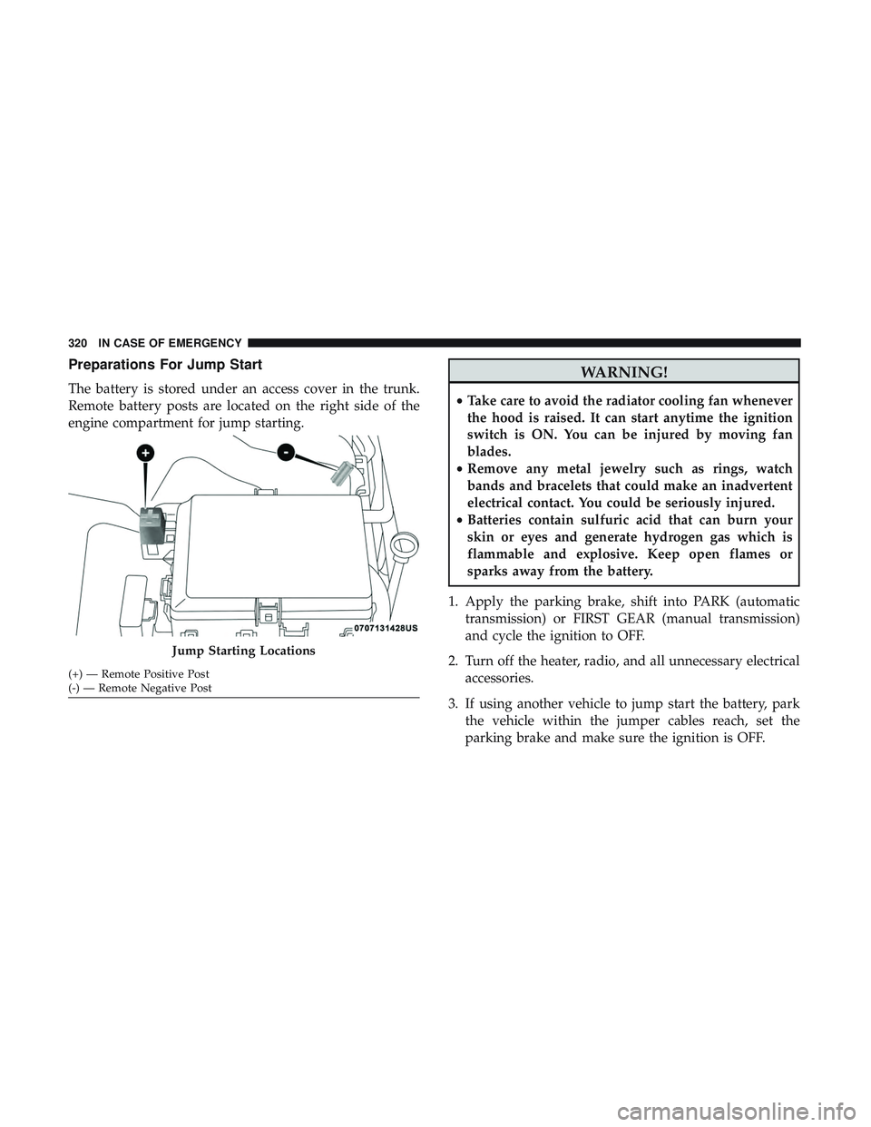
Preparations For Jump Start
The battery is stored under an access cover in the trunk.
Remote battery posts are located on the right side of the
engine compartment for jump starting.
WARNING!
•Take care to avoid the radiator cooling fan whenever
the hood is raised. It can start anytime the ignition
switch is ON. You can be injured by moving fan
blades.
• Remove any metal jewelry such as rings, watch
bands and bracelets that could make an inadvertent
electrical contact. You could be seriously injured.
• Batteries contain sulfuric acid that can burn your
skin or eyes and generate hydrogen gas which is
flammable and explosive. Keep open flames or
sparks away from the battery.
1. Apply the parking brake, shift into PARK (automatic transmission) or FIRST GEAR (manual transmission)
and cycle the ignition to OFF.
2. Turn off the heater, radio, and all unnecessary electrical accessories.
3. If using another vehicle to jump start the battery, park the vehicle within the jumper cables reach, set the
parking brake and make sure the ignition is OFF.
Jump Starting Locations
(+) — Remote Positive Post
(-) — Remote Negative Post 320 IN CASE OF EMERGENCY
Page 324 of 500
Disconnecting The Jumper Cables
1. Disconnect the negative(-)end of the jumper cable from
the remote negative (-)post of the vehicle with the
discharged battery.
2. Disconnect the opposite end of the negative (-)jumper
cable from the negative (-)post of the booster battery.
3. Disconnect the positive (+)end of the jumper cable from
the positive (+)post of the booster battery.
4. Disconnect the opposite end of the positive (+)jumper
cable from the remote positive (+)post of the vehicle
with the discharged battery.
If frequent jump starting is required to start your vehicle
you should have the battery and charging system in-
spected at an authorized dealer.
CAUTION!
Accessories plugged into the vehicle power outlets
draw power from the vehicle’s battery, even when not
in use (i.e., cellular devices, etc.). Eventually, if plugged
in long enough without engine operation, the vehicle’s
battery will discharge sufficiently to degrade battery
life and/or prevent the engine from starting.
IF YOUR ENGINE OVERHEATS
In any of the following situations, you can reduce the
potential for overheating by taking the appropriate action.
• On the highways — slow down.
• In city traffic — while stopped, place the transmission in
NEUTRAL, but do not increase the engine idle speed
while preventing vehicle motion with the brakes.
NOTE: There are steps that you can take to slow down an
impending overheat condition:
• If your air conditioner (A/C) is on, turn it off. The A/C
system adds heat to the engine cooling system and
turning the A/C off can help remove this heat.
• You can also turn the temperature control to maximum
heat, the mode control to floor and the blower control to
high. This allows the heater core to act as a supplement
to the radiator and aids in removing heat from the
engine cooling system.
322 IN CASE OF EMERGENCY