Page 303 of 532

JACKING AND TIRE CHANGING
WARNING!
•Do not attempt to change a tire on the side of the
vehicle close to moving traffic. Pull far enough off
the road to avoid the danger of being hit when
operating the jack or changing the wheel.
• Being under a jacked-up vehicle is dangerous. The
vehicle could slip off the jack and fall on you. You
could be crushed. Never put any part of your body
under a vehicle that is on a jack. If you need to get
under a raised vehicle, take it to a service center
where it can be raised on a lift.
• Never start or run the engine while the vehicle is on
a jack.
• The jack is designed to be used as a tool for changing
tires only. The jack should not be used to lift the
vehicle for service purposes. The vehicle should be
jacked on a firm level surface only. Avoid ice or
slippery areas.
Jack Location/Spare Tire Stowage
The jack and spare tire are both stowed under an access
cover in the trunk. Follow these steps to access the jack and
spare tire.
NOTE: The spare tire must be removed in order to access
the jack.
1. Open the trunk.
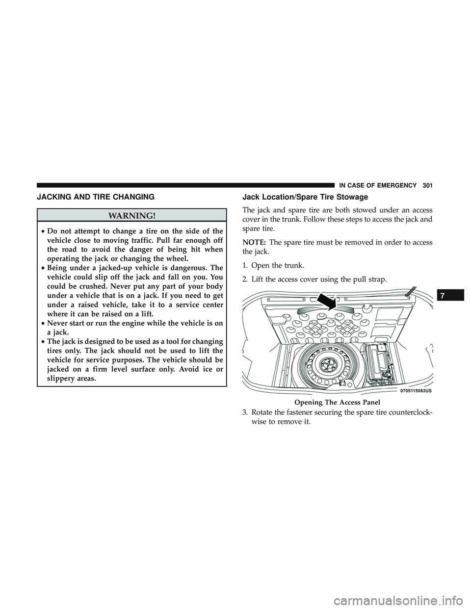
2. Lift the access cover using the pull strap.
3. Rotate the fastener securing the spare tire counterclock- wise to remove it.
Opening The Access Panel
7
IN CASE OF EMERGENCY 301
Page 304 of 532
4. Remove the spare tire.
5. Rotate the fastener securing the jack counterclockwise toremove it. 6. Remove the jack and lug wrench assembly from under
the spare tire. Turn the jack screw to the left to loosen the
lug wrench, and remove the wrench from the jack
assembly.
WARNING!
A loose tire or jack thrown forward in a collision or
hard stop could endanger the occupants of the vehicle.
Always stow the jack parts and the spare tire in the
places provided. Have the deflated (flat) tire repaired
or replaced immediately.
Spare Tire FastenerJack Fastener
302 IN CASE OF EMERGENCY
Page 307 of 532

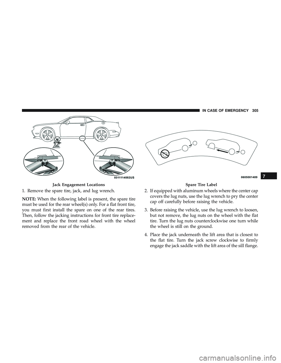
1. Remove the spare tire, jack, and lug wrench.
NOTE:When the following label is present, the spare tire
must be used for the rear wheel(s) only. For a flat front tire,
you must first install the spare on one of the rear tires.
Then, follow the jacking instructions for front tire replace-
ment and replace the front road wheel with the wheel
removed from the rear of the vehicle. 2. If equipped with aluminum wheels where the center cap
covers the lug nuts, use the lug wrench to pry the center
cap off carefully before raising the vehicle.
3. Before raising the vehicle, use the lug wrench to loosen, but not remove, the lug nuts on the wheel with the flat
tire. Turn the lug nuts counterclockwise one turn while
the wheel is still on the ground.
4. Place the jack underneath the lift area that is closest to the flat tire. Turn the jack screw clockwise to firmly
engage the jack saddle with the lift area of the sill flange.
Jack Engagement LocationsSpare Tire Label
7
IN CASE OF EMERGENCY 305
Page 308 of 532
NOTE:If the vehicle is too low for jack placement, slide the
jack on its side and rotate it up into position.
5. Raise the vehicle just enough to remove the flat tire andinstall the spare tire.
WARNING!
Raising the vehicle higher than necessary can make the
vehicle less stable. It could slip off the jack and hurt
someone near it. Raise the vehicle only enough to
remove the tire.
6. Remove the lug nuts and tire.
Front Jacking Location
Rear Jacking Location
306 IN CASE OF EMERGENCY
Page 309 of 532

7. Mount the spare tire.
CAUTION!
Do not attempt to raise the vehicle by jacking on
locations other than those indicated.NOTE:
•For vehicles so equipped, do not attempt to install a
center cap or wheel cover on the compact spare.
• Refer to “Compact Spare Tire” and to “Limited-Use
Spare” under “Tires—General Information” in “Servic-
ing And Maintenance” for additional warnings, cau-
tions, and information about the spare tire, its use, and
operation.
8. Install the lug nuts with the cone shaped end of the lug nut toward the wheel. Lightly tighten the lug nuts.
WARNING!
To avoid the risk of forcing the vehicle off the jack, do
not tighten the wheel nuts fully until the vehicle has
been lowered. Failure to follow this warning may
result in serious injury.
9. Lower the vehicle to the ground by turning the jack handle counterclockwise.
10. Refer to “Torque Specifications” in “Technical Specifi- cations” section for proper lug nut torque.
Mounting Spare Tire
7
IN CASE OF EMERGENCY 307
Page 310 of 532

11. Stow the jack, tools and flat tire. Make sure the base ofthe jack faces the front of the vehicle before tightening
down the fastener.
WARNING!
A loose tire or jack thrown forward in a collision or
hard stop could endanger the occupants of the vehicle.
Always stow the jack parts and the spare tire in the
places provided. Have the deflated (flat) tire repaired
or replaced immediately.
Road Tire Installation
1. Mount the road tire on the axle.
2. Install the remaining lug nuts with the cone shaped endof the nut toward the wheel. Lightly tighten the lug
nuts.
WARNING!
To avoid the risk of forcing the vehicle off the jack, do
not tighten the wheel nuts fully until the vehicle has
been lowered. Failure to follow this warning may
result in serious injury. 3. Lower the vehicle to the ground by turning the jack
handle counterclockwise.
4. Refer to “Torque Specifications” in “Technical Specifica- tions” for proper lug nut torque.
5. After 25 miles (40 km), check the lug nut torque with a torque wrench to ensure that all lug nuts are properly
seated against the wheel.
TIRE SERVICE KIT — IF EQUIPPED
Small punctures up to 1/4 inch (6 mm) in the tire tread can
be sealed with Tire Service Kit. Foreign objects (e.g., screws
or nails) should not be removed from the tire. Tire Service
Kit can be used in outside temperatures down to approxi-
mately -4°F (-20°C).
This kit will provide a temporary tire seal, allowing you to
drive your vehicle up to 100 miles (160 km) with a
maximum speed of 50 mph (80 km/h).
308 IN CASE OF EMERGENCY
Page 338 of 532

�RAISING THE VEHICLE ..................373
� TIRES ............................... .374
▫ Tire Safety Information ..................374
▫ Tires — General Information ..............383
▫ Tire Types ........................... .389
▫ Spare Tires — If Equipped ................390
▫ Wheel And Wheel Trim Care ..............393
▫ Tire Chains (Traction Devices) .............394
▫ Tire Rotation Recommendations .............395
� DEPARTMENT OF TRANSPORTATION
UNIFORM TIRE QUALITY GRADES ..........396
▫ Treadwear ........................... .396
▫ Traction Grades ....................... .396▫
Temperature Grades .....................396
� VEHICLE STORAGE .....................397
� BODYWORK .......................... .397
▫ Protection From Atmospheric Agents ........397
▫ Body And Underbody Maintenance ..........398
▫ Preserving The Bodywork .................398
� INTERIORS ........................... .399
▫ Seats And Fabric Parts ...................399
▫ Plastic And Coated Parts ..................400
▫ Leather Parts ......................... .400
▫ Glass Surfaces ........................ .401
336 SERVICING AND MAINTENANCE
Page 376 of 532

TIRES
Tire Safety Information
Tire safety information will cover aspects of the following
information: Tire Markings, Tire Identification Numbers,
Tire Terminology and Definitions, Tire Pressures, and Tire
Loading.
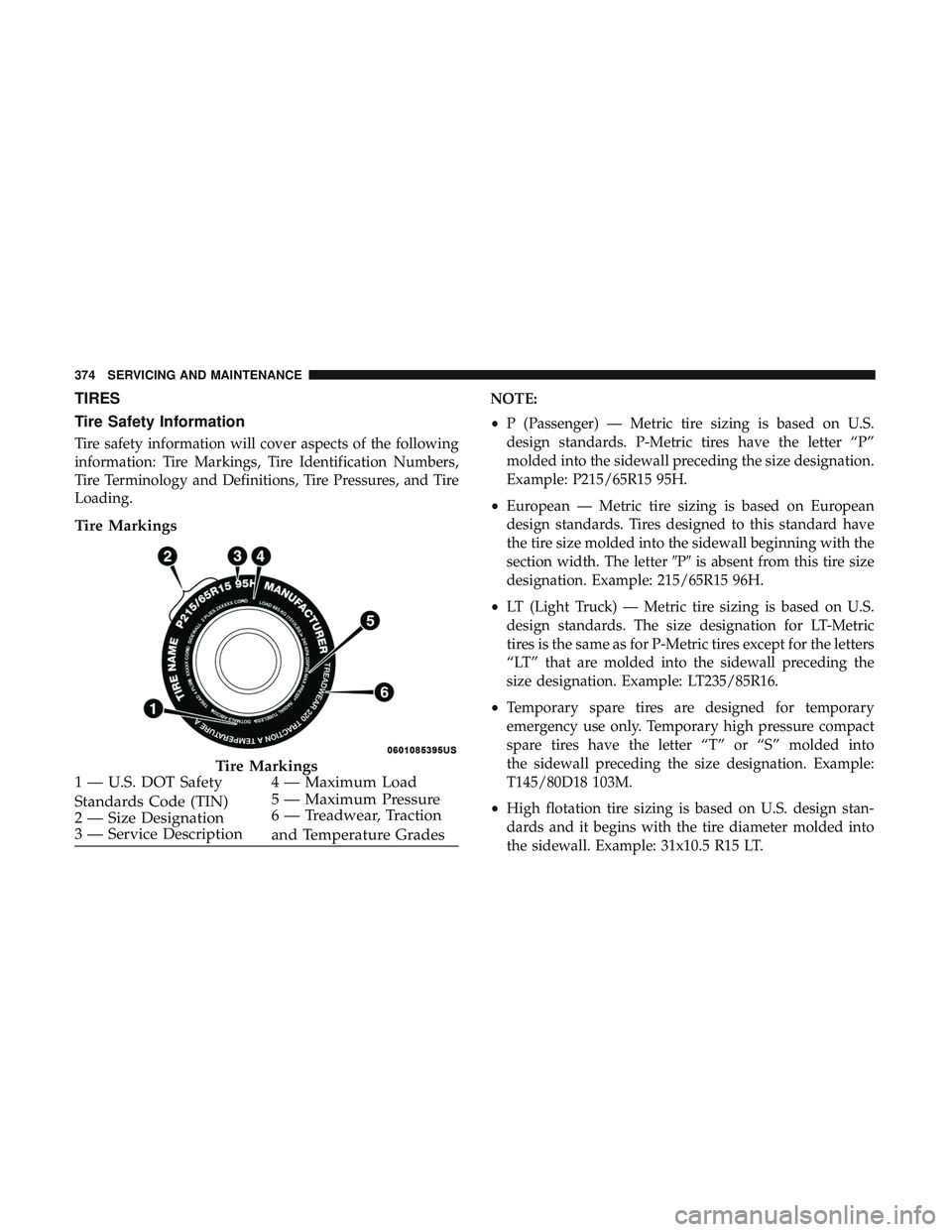
Tire Markings
NOTE:
•P (Passenger) — Metric tire sizing is based on U.S.
design standards. P-Metric tires have the letter “P”
molded into the sidewall preceding the size designation.
Example: P215/65R15 95H.
• European — Metric tire sizing is based on European
design standards. Tires designed to this standard have
the tire size molded into the sidewall beginning with the
section width. The letter �P�is absent from this tire size
designation. Example: 215/65R15 96H.
• LT (Light Truck) — Metric tire sizing is based on U.S.
design standards. The size designation for LT-Metric
tires is the same as for P-Metric tires except for the letters
“LT” that are molded into the sidewall preceding the
size designation. Example: LT235/85R16.
• Temporary spare tires are designed for temporary
emergency use only. Temporary high pressure compact
spare tires have the letter “T” or “S” molded into
the sidewall preceding the size designation. Example:
T145/80D18 103M.
• High flotation tire sizing is based on U.S. design stan-
dards and it begins with the tire diameter molded into
the sidewall. Example: 31x10.5 R15 LT.
Tire Markings
1 — U.S. DOT Safety
Standards Code (TIN) 4 — Maximum Load
2 — Size Designation 5 — Maximum Pressure
3 — Service Description 6 — Treadwear, Traction
and Temperature Grades
374 SERVICING AND MAINTENANCE