2019 CHRYSLER PACIFICA audio
[x] Cancel search: audioPage 29 of 718

KeySense Unique Splash Screen
At start-up the KeySense splash screen should inform the
driver that the vehicle will be functioning in KeySense
mode when the KeySense key is in use.
Start Up Display Features
•Unique splash screen graphic
• Telltale
illuminated
•After unique splash screen, and after stored messages
are cycled, then start-up KeySense messages (Range &
Max Speed) are displayed The following features are always enabled when this key is
in use:
•
Entertainment Audio Muted if 1st row occupied Seat
Belts are not Fastened
• Consistent Seat Belt Unfastened Chime
• Maximum Radio Volume limited to 15 out of 39
• Daytime Running Lights
• Headlights with Wipers
• Rain Sensing Auto Wipers
• Auto Dim High Beams
For additional information please refer to “Uconnect Set-
tings” in “Multimedia” for further information.
General Information
The following regulatory statement applies to all radio
frequency (RF) devices equipped in this vehicle:
This device complies with Part 15 of the FCC Rules and
with Industry Canada license-exempt RSS standard(s).
Operation is subject to the following two conditions:
1. This device may not cause harmful interference, and
KeySense Key Fob
3
GETTING TO KNOW YOUR VEHICLE 27
Page 179 of 718

Power Inverter — If Equipped
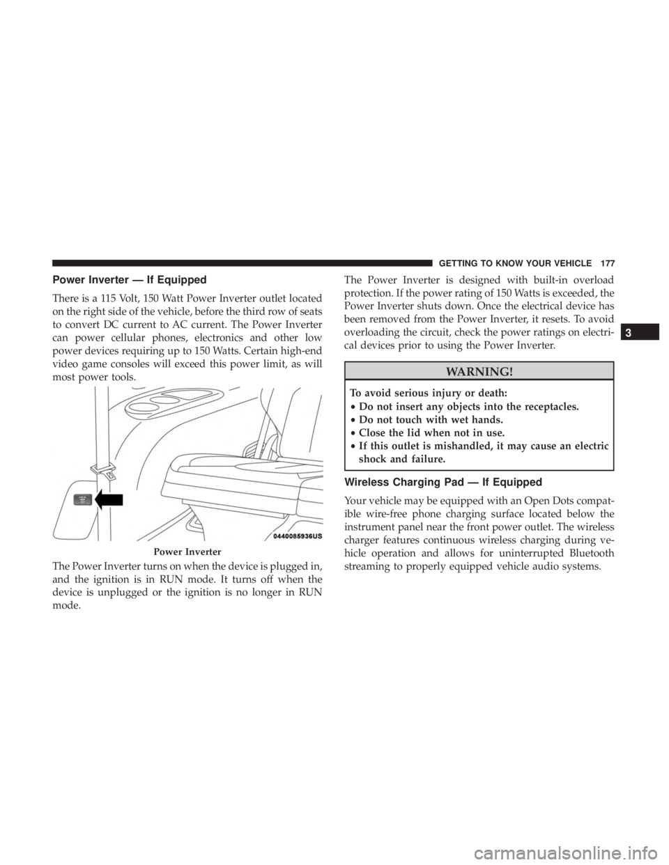
There is a 115 Volt, 150 Watt Power Inverter outlet located
on the right side of the vehicle, before the third row of seats
to convert DC current to AC current. The Power Inverter
can power cellular phones, electronics and other low
power devices requiring up to 150 Watts. Certain high-end
video game consoles will exceed this power limit, as will
most power tools.
The Power Inverter turns on when the device is plugged in,
and the ignition is in RUN mode. It turns off when the
device is unplugged or the ignition is no longer in RUN
mode.The Power Inverter is designed with built-in overload
protection. If the power rating of 150 Watts is exceeded, the
Power Inverter shuts down. Once the electrical device has
been removed from the Power Inverter, it resets. To avoid
overloading the circuit, check the power ratings on electri-
cal devices prior to using the Power Inverter.
WARNING!
To avoid serious injury or death:
•
Do not insert any objects into the receptacles.
• Do not touch with wet hands.
• Close the lid when not in use.
• If this outlet is mishandled, it may cause an electric
shock and failure.
Wireless Charging Pad — If Equipped
Your vehicle may be equipped with an Open Dots compat-
ible wire-free phone charging surface located below the
instrument panel near the front power outlet. The wireless
charger features continuous wireless charging during ve-
hicle operation and allows for uninterrupted Bluetooth
streaming to properly equipped vehicle audio systems.
Power Inverter
3
GETTING TO KNOW YOUR VEHICLE 177
Page 196 of 718

•Right Arrow Button
Push and release the rightarrow button to access
the information screens or submenu screens of a
main menu item.
• Back/Left Arrow Button
Push and release the leftarrow button to access
the information screens or submenu screens of a
main menu item.
• OK Button
Push the OKbutton to access/select the information
screens or submenu screens of a Main Menu item. Push
and hold the OKbutton for two seconds to reset
displayed/selected features that can be reset.
The instrument cluster display (base/premium cluster)
features a driver-interactive display that is located in the
center of the instrument cluster, and may include the
following menu/submenu items:
• Speedometer
• Vehicle Info
• Driver Assist — If Equipped •
Fuel Economy
• Trip (Trip A/Trip B)
• Stop/Start — If Equipped
• Audio
• Messages
• Screen Setup
Oil Life Reset
•Your vehicle is equipped with an engine oil change
indicator system. The “Oil Change Required” message
will display for approximately five seconds after a single
chime has sounded, to indicate the next scheduled oil
change interval. The engine oil change indicator system
is duty cycle based, which means the engine oil change
interval may fluctuate, dependent upon your personal
driving style.
• Unless reset, this message will continue to display each
time the ignition is cycled to the ON/RUN position.
• To reset the oil change indicator after performing the
scheduled maintenance, refer to the following proce-
dure.
194 GETTING TO KNOW YOUR INSTRUMENT PANEL
Page 201 of 718

•Elapsed Time
Hold the OKbutton to reset feature information.
Stop/Start – If Equipped
Push and release the upordown arrow button until the
Stop/Start menu title is displayed in the instrument cluster
display.
Audio
Push and release the upordown arrow button until the
Audio Menu displays in the instrument cluster display.
Messages
Push and release the upordown arrow button until
Messages is highlighted in the instrument cluster display. This feature shows the number of stored warning mes-
sages. Pushing the
rightarrow button will allow you to see
what the stored messages are.
NOTE: The popup messages indicate the status of the
system and/or the conditions that need to be met. Mes-
sages remain in the stored stack until condition is cleared.
Screen Setup
Push and release the upordown arrow button until the
Screen Setup Menu displays in the instrument cluster
display. Push and release the OKbutton to enter the
submenus. The Screen Setup feature allows you to change
what information is displayed in the instrument cluster as
well as the location that information is displayed.
Premium Instrument Cluster Display Screen Setup Options:
1 — Lower Left
• None
• Compass (Default)
• Outside Temp.
• Time
• Range
• Average/Current (MPG, L/100km, or km/L)
• Trip A Distance
• Trip B Distance 4
GETTING TO KNOW YOUR INSTRUMENT PANEL 199
Page 202 of 718

Premium Instrument Cluster Display Screen Setup Options:
2 — Center
• None
• Compass
• Outside Temp.
• Time
• Range
• Average/Current (MPG, L/100km, or km/L)
• Trip A Distance
• Trip B Distance
• Audio
• Digital Speed
• Menu Title (Default)
3 — Lower Right•None
• Compass
• Outside Temp. (Default)
• Time
• Range
• Average/Current (MPG, L/100km, or km/L)
• Trip A Distance
• Trip B Distance
4 — Odometer (Premium Instrument Cluster)•Show — Default
• Hide (Odometer will still appear when door is open)
5 — Defaults•Restore
• Cancel
200 GETTING TO KNOW YOUR INSTRUMENT PANEL
Page 203 of 718

Base Instrument Cluster Display Screen Setup Options:
1 — Upper Left
• None
• Compass (Default)
• Outside Temp.
• Time
• Range
• Average/Current (MPG, L/100km, or km/L)
2 — Upper Right•None
• Compass
• Outside Temp (Default)
• Time
• Range
• Average/Current (MPG, L/100km, or km/L)
3 — Center•None
• Compass
• Outside Temp.
• Time
• Range
• Average/Current (MPG, L/100km, or km/L)
• Trip A Distance
• Trip B Distance
• Audio Menu Title
• Menu Title (Default)
• Digital Speed 4
GETTING TO KNOW YOUR INSTRUMENT PANEL 201
Page 205 of 718

•HVAC System
• 150W Power Inverter System
• Audio and Telematics System
Loss of the battery charge may indicate one or more of the
following conditions:
• The charging system cannot deliver enough electrical
power to the vehicle system because the electrical loads
are larger than the capability of charging system. The
charging system is still functioning properly.
• Turning on all possible vehicle electrical loads (e.g.
HVAC to max settings, exterior and interior lights,
overloaded power outlets +12V, 150W, USB ports) dur-
ing certain driving conditions (city driving, towing,
frequent stopping).
• Installing options like additional lights, upfitter electri-
cal accessories, audio systems, alarms and similar de-
vices.
• Unusual driving cycles (short trips separated by long
parking periods). •
The vehicle was parked for an extended period of time
(weeks, months).
• The battery was recently replaced and was not charged
completely.
• The battery was discharged by an electrical load left on
when the vehicle was parked.
• The battery was used for an extended period with the
engine not running to supply radio, lights, chargers,
+12V portable appliances like vacuum cleaners, game
consoles and similar devices.
What to do when an electrical load reduction action
message is present (“Battery Saver On” or “Battery Saver
Mode”)
During a trip:
• Reduce power to unnecessary loads if possible:
– Turn off redundant lights (interior or exterior)
– Check what may be plugged in to power outlets +12V, 150W, USB ports
– Check HVAC settings (blower, temperature)
– Check the audio settings (volume)
4
GETTING TO KNOW YOUR INSTRUMENT PANEL 203
Page 206 of 718

After a trip:
•Check if any aftermarket equipment was installed (ad-
ditional lights, upfitter electrical accessories, audio sys-
tems, alarms) and review specifications if any (load and
Ignition Off Draw currents).
• Evaluate the latest driving cycles (distance, driving time
and parking time).
• The vehicle should have service performed if the mes-
sage is still present during consecutive trips and the
evaluation of the vehicle and driving pattern did not
help to identify the cause.
TRIP COMPUTER
The Trip Computer is located in the instrument cluster
display. Push and release the up or down arrow button
until “Trip Info” is highlighted in the instrument cluster
display. Push OK to enter the menu. Navigate between Trip
A or Trip B by using the right and left arrows.
For each trip the following information will be displayed:
Trip A
• Shows the total distance traveled for Trip A since the last
reset. •
Shows the Average MPG for Trip A since the last reset.
• Shows the elapsed time traveled for Trip A since the last
reset. Elapsed time will increment when the ignition
switch is in the ON or START position.
Trip B
• Shows the total distance traveled for Trip B since the last
reset.
• Shows the Average MPG for Trip B since the last reset.
• Shows the elapsed time traveled for Trip B since the last
reset. Elapsed time will increment when the ignition
switch is in the ON or START position.
To Reset A Trip Function
Push and hold the OK button to reset the currently
displayed trip.
WARNING LIGHTS AND MESSAGES
The warning/indicator lights will illuminate in the instru-
ment panel together with a dedicated message and/or
acoustic signal when applicable. These indications are
indicative and precautionary and as such must not be
considered as exhaustive and/or alternative to the infor-
mation contained in the Owner ’s Manual, which you are
204 GETTING TO KNOW YOUR INSTRUMENT PANEL