Page 158 of 492
 — If Equipped
The Blind Spot Monitoring (BSM) system uses two radar
sensors, located inside the rear bumper fascia, to detect
highway licensable")
AUXILIARY DRIVING SYSTEMS
Blind Spot Monitoring (BSM) — If Equipped
The Blind Spot Monitoring (BSM) system uses two radar
sensors, located inside the rear bumper fascia, to detect
highway licensable vehicles (automobiles, trucks, motorcycles,
etc.) that enter the blind spot zones from the rear/front/side of
the vehicle.
When the vehicle is started, the BSM warning light will
momentarily illuminate in both outside rear view mirrors
to let the driver know that the system is operational. The
BSM system sensors operate when the vehicle is in any
forward gear or REVERSE.The BSM detection zone covers approximately one lane
width on both sides of the vehicle 12 ft (3.8 m). The zone
length starts at the outside rear view mirror and extends
approximately 10 ft (3 m) beyond the rear bumper of the
vehicle. The BSM system monitors the detection zones on
both sides of the vehicle when the vehicle speed reaches
approximately 6 mph (10 km/h) or higher and will alert
the driver of vehicles in these areas.
Rear Detection Zones
BSM Warning Light
156 SAFETY
Page 282 of 492

When enabled, active guide lines are overlaid on the image
to illustrate the width of the vehicle and its projected
backup path based on the steering wheel position. The
active guide lines will show separate zones that will help
indicate the distance to the rear of the vehicle.
When manually activated, a counter will be initiated after
the vehicle speed is above 8 mph (13 km/h). The rear view
camera image will turn off when this counter reaches 10
seconds. The counter will be reset when the vehicle speed
is 8 mph (13 km/h) or below.If the vehicle speed remains below 8 mph (13 km/h), the
rear view camera image will continue to be displayed until
the transmission is shifted into PARK, the vehicle’s ignition
is cycled to the OFF position, or the image defeat [X] button
is pressed.
Different colored zones indicate the distance to the rear of
the vehicle.
The following table shows the approximate distances for
each zone:
Zone
Distance To The Rear Of The Vehicle
Red 0 - 1 ft (0 - 30 cm)
Yellow 1 ft - 6.5 ft (30 cm - 2 m)
Green 6.5 ft or greater (2 m or greater)
280 STARTING AND OPERATING
Page 289 of 492

The total load must be limited so that you do not exceed
the GVWR. Refer to “Vehicle Loading/Vehicle Certification
Label” in “Starting And Operating” for further informa-
tion.
Gross Trailer Weight (GTW)
The GTW is the weight of the trailer plus the weight of all
cargo, consumables, and equipment (permanent or tempo-
rary) loaded in or on the trailer in its�loaded and ready for
operation� condition.
The recommended way to measure GTW is to put your
fully loaded trailer on a vehicle scale. The entire weight of
the trailer must be supported by the scale.
Gross Combination Weight Rating (GCWR)
The GCWR is the total allowable weight of your vehicle
and trailer when weighed in combination.
Gross Axle Weight Rating (GAWR)
The GAWR is the maximum capacity of the front and rear
axles. Distribute the load over the front and rear axles
evenly. Make sure that you do not exceed either front or
rear GAWR. Refer to “Vehicle Loading/Vehicle Certifica-
tion Label” in “Starting And Operating” for further infor-
mation.
WARNING!
It is important that you do not exceed the maximum
front or rear GAWR. A dangerous driving condition
can result if either rating is exceeded. You could lose
control of the vehicle and have a collision.
Tongue Weight (TW)
The tongue weight is the downward force exerted on the
hitch ball by the trailer. You must consider this as part of
the load on your vehicle.
Trailer Frontal Area
The frontal area is the maximum height multiplied by the
maximum width of the front of a trailer.
Trailer Sway Control
The trailer sway control can be a mechanical telescoping
link that can be installed between the hitch receiver and the
trailer tongue that typically provides adjustable friction
associated with the telescoping motion to dampen any
unwanted trailer swaying motions while traveling.
6
STARTING AND OPERATING 287
Page 376 of 492
 — Metric tire sizing is based on U.S.
design standards. P-Metric tires have the letter “P”
molded into the sidewall preceding the size designation.
Example: P215/65R15 95H")
NOTE:
•P (Passenger) — Metric tire sizing is based on U.S.
design standards. P-Metric tires have the letter “P”
molded into the sidewall preceding the size designation.
Example: P215/65R15 95H.
• European — Metric tire sizing is based on European
design standards. Tires designed to this standard have
the tire size molded into the sidewall beginning with the
section width. The letter �P�is absent from this tire size
designation. Example: 215/65R15 96H.
• LT (Light Truck) — Metric tire sizing is based on U.S.
design standards. The size designation for LT-Metric
tires is the same as for P-Metric tires except for the letters
“LT” that are molded into the sidewall preceding the
size designation. Example: LT235/85R16. •
Temporary spare tires are designed for temporary emer-
gency use only. Temporary high pressure compact spare
tires have the letter “T” or “S” molded into the sidewall
preceding the size designation. Example: T145/80D18
103M.
• High flotation tire sizing is based on U.S. design stan-
dards and it begins with the tire diameter molded into
the sidewall. Example: 31x10.5 R15 LT.
374 SERVICING AND MAINTENANCE
Page 377 of 492
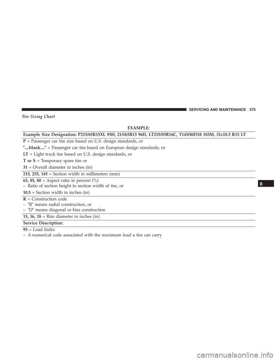
Tire Sizing Chart
EXAMPLE:
Example Size Designation: P215/65R15XL 95H, 215/65R15 96H, LT235/85R16C, T145/80D18 103M, 31x10.5 R15 LT
P = Passenger car tire size based on U.S. design standards, or
�....blank....� = Passenger car tire based on European design standards, or
LT = Light truck tire based on U.S. design standards, or
TorS= Temporary spare tire or
31 = Overall diameter in inches (in)
215, 235, 145 = Section width in millimeters (mm)
65, 85, 80 = Aspect ratio in percent (%)
–Ratio of section height to section width of tire, or
10.5 = Section width in inches (in)
R = Construction code
–�R� means radial construction, or
–�D� means diagonal or bias construction
15, 16, 18 = Rim diameter in inches (in)
Service Description:
95 = Load Index
–A numerical code associated with the maximum load a tire can carry
8
SERVICING AND MAINTENANCE 375