2019 CHEVROLET CORVETTE lock
[x] Cancel search: lockPage 262 of 367

Chevrolet Corvette Owner Manual (GMNA-Localizing-U.S./Canada/Mexico-
12032182) - 2019 - crc - 5/8/18
Vehicle Care 261
FusesUsage
31 Heated seat module / run,crank
supply
32 Starter
36 Body control module 7
39 Intrusion module / Human machine
interface module
40 Steering column lock
41 ABS valves
43 - / Fuel tank zone module batt
44 Center stack
45 Auxiliary outlet
46 Radio
47 Display
48 Interior rearview mirror
49 Logistics Fuses
Usage
50 Engine / Transmission
51 Ignition –odd
52 Ignition –even
53 Fuel pump prime / Miscellaneous
powertrain loads
54 - / Fuel injector control module
power ignition 2
55 Engine control module 1
58 Data link connector
63 Seat fan
64 Fuel pump power module
65 Cluster
67 Exhaust valve 1
71 Horn
73 –/ Fuel tank zone
module ignition
74 Headlamp wash Fuses
Usage
75 AC clutch
76 –/ Rear
transmission
coolant pump
77 Engine outside position
78 Engine control module 2 /
Transmission
control module
79 Electric parking brake
81 Continuous variable real time
dampening
82 Intercooler
83 Left headlamp
84 Right headlamp
85 High-beam headlamps
86 Washer pump
87 Exhaust valve 2
88 Reverse lockout
Page 263 of 367

Chevrolet Corvette Owner Manual (GMNA-Localizing-U.S./Canada/Mexico-
12032182) - 2019 - crc - 5/8/18
262 Vehicle Care
FusesUsage
90 Electronic Limited slip differential 1
92 Vacuum pump
93 Transmission cooling rear fan 1
94 Electronic Limited slip differential 2
95 Transmission control module
97 Canister vent valve
Relays Usage
K2 –/ Engine control
module
K3 Starter
K4 Front wiper, Low-High
K5 Run-Crank
K8 Front wiper on off
K10 Fuel pump prime K11 Engine control module /– Relays
Usage
K15 Headlamp washer
K17 AC control
K18 Vacuum pump
K21 Low beam headlamps
Fuses Usage
1 Spare
2 Spare
3 Spare
4 Spare
5 Spare
6 Spare
7 Spare
8 Spare
9 Spare
10 Spare
11 SpareRear Compartment Fuse
Block
The rear compartment fuse block is
in the rear of the vehicle, on top of
the battery.
Page 266 of 367

Chevrolet Corvette Owner Manual (GMNA-Localizing-U.S./Canada/Mexico-
12032182) - 2019 - crc - 5/8/18
Vehicle Care 265
FusesUsage
38 –
39 –
40 –
41 –
42 –
43 –
44 –
Relays Usage
R1 –
R2 Rear window defogger
R3 –
R4 Front accessory power outlet
R5 Theft (door lock security)Wheels and Tires
Tires
Every new GM vehicle has
high-quality tires made by a
leading tire manufacturer. See
the warranty manual for
information regarding the tire
warranty and where to get
service. For additional
information refer to the tire
manufacturer.
{Warning
.Poorly maintained and
improperly used tires are
dangerous.
.Overloading the tires can
cause overheating as a
result of too much
flexing. There could be a
blowout and a serious
crash. See Vehicle Load
Limits 0175.
(Continued)
Warning (Continued)
.Underinflated tires pose
the same danger as
overloaded tires. The
resulting crash could
cause serious injury.
Check all tires frequently
to maintain the
recommended pressure.
Tire pressure should be
checked when the tires
are cold.
.Overinflated tires are
more likely to be cut,
punctured, or broken by
a sudden impact —such
as when hitting a pothole.
Keep tires at the
recommended pressure.
.Worn or old tires can
cause a crash. If the
tread is badly worn,
replace them.
(Continued)
Page 283 of 367

Chevrolet Corvette Owner Manual (GMNA-Localizing-U.S./Canada/Mexico-
12032182) - 2019 - crc - 5/8/18
282 Vehicle Care
Warning (Continued)
after many miles of driving.
A tire and/or wheel could fail
suddenly and cause a crash.
Use only radial-ply tires with
the wheels on the vehicle.
If the vehicle tires must be
replaced with a tire that does not
have a TPC Spec number, make
sure they are the same size,
load range, speed rating, and
construction (radial) as the
original tires.
Vehicles that have a tire
pressure monitoring system
could give an inaccurate
low-pressure warning if non-TPC
Spec rated tires are installed.
See Tire Pressure Monitor
Operation 0276. The Tire and Loading
Information label indicates the
original equipment tires on the
vehicle. See
Vehicle Load Limits
0 175.
Different Size Tires and
Wheels
If wheels or tires are installed that
are a different size than the original
equipment wheels and tires, vehicle
performance, including its braking,
ride and handling characteristics,
stability, and resistance to rollover
may be affected. If the vehicle has
electronic systems such as antilock
brakes, rollover airbags, traction
control, electronic stability control,
or All-Wheel Drive, the performance
of these systems can also be
affected.
{Warning
If different sized wheels are used,
there may not be an acceptable
level of performance and safety if
(Continued)
Warning (Continued)
tires not recommended for those
wheels are selected. This
increases the chance of a crash
and serious injury. Only use GM
specific wheel and tire systems
developed for the vehicle, and
have them properly installed by a
GM certified technician.
See Buying New Tires 0280 and
Accessories and Modifications
0 220.
Uniform Tire Quality
Grading
The following information relates
to the system developed by the
United States National Highway
Traffic Safety Administration
(NHTSA), which grades tires by
treadwear, traction, and
temperature performance. This
applies only to vehicles sold in
the United States. The grades
are molded on the sidewalls of
Page 291 of 367

Chevrolet Corvette Owner Manual (GMNA-Localizing-U.S./Canada/Mexico-
12032182) - 2019 - crc - 5/8/18
290 Vehicle Care
4. Pressure Deflation Button
5. Tire Sealant Canister
6. Sealant/Air Hose (Clear)
7. Air Only Hose (Black)
8. Power Plug
9. Canister Release Button(Under Sealant/Air Hose)
When using the tire sealant and
compressor kit during cold
temperatures, warm the kit in a
heated environment for five minutes.
This will help to inflate the tire
faster.
If a tire goes flat, avoid further tire
and wheel damage by driving slowly
to a level place. Turn on the hazard
warning flashers. See Hazard
Warning Flashers 0142.
See If a Tire Goes Flat 0286 for
other important safety warnings.
Do not remove any objects that
have penetrated the tire.
1. Remove the tire sealant and compressor kit from its storage
location. See Storing the Tire
Sealant and Compressor Kit
0 294. 2. Unwrap the sealant/air hose (6)
and the power plug (8).
3. Place the kit on the ground. Make sure the tire valve stem
is positioned close to the
ground so the hose will
reach it.
4. Remove the valve stem cap from the flat tire by turning it
counterclockwise.
5. Attach the sealant/air hose (6) onto the tire valve stem. Turn it
clockwise until it is tight.
6. Plug the power plug (8) into the accessory power outlet in the
vehicle. Unplug all items from
other accessory power outlets.
See Power Outlets 0101.
If the vehicle has an accessory
power outlet, do not use the
cigarette lighter.
If the vehicle only has a
cigarette lighter, use the
cigarette lighter.
Do not pinch the power plug
cord in the door or window. 7. Start the vehicle. The vehicle
must be running while using
the air compressor.
8. Press and turn the selector switch (1) counterclockwise to
the Sealant + Air position.
9. Press the on/off button (2) to turn the tire sealant and
compressor kit on.
The compressor will inject
sealant and air into the tire.
The pressure gauge (3) will
initially show a high pressure
while the compressor pushes
the sealant into the tire. Once
the sealant is completely
dispersed into the tire, the
pressure will quickly drop and
start to rise again as the tire
inflates with air only.
10. Inflate the tire to the recommended inflation
pressure using the pressure
gauge (3). The recommended
inflation pressure can be found
on the Tire and Loading
Information label. See Tire
Pressure 0274.
Page 292 of 367

Chevrolet Corvette Owner Manual (GMNA-Localizing-U.S./Canada/Mexico-
12032182) - 2019 - crc - 5/8/18
Vehicle Care 291
The pressure gauge (3) may
read higher than the actual tire
pressure while the compressor
is on. Turn the compressor off
to get an accurate reading. The
compressor may be turned on/
off until the correct pressure is
reached.
Caution
If the recommended pressure
cannot be reached after
approximately 25 minutes, the
vehicle should not be driven
farther. The tire is too severely
damaged and the tire sealant and
compressor kit cannot inflate the
tire. Remove the power plug from
the accessory power outlet and
unscrew the inflating hose from
the tire valve. SeeRoadside
Assistance Program 0334.
11. Press the on/off button (2) to turn the tire sealant and
compressor kit off. The tire is not sealed and will
continue to leak air until the
vehicle is driven and the
sealant is distributed in the tire,
therefore, Steps 12–18 must be
done immediately after
Step 11.
Be careful while handling the
tire sealant and compressor kit
as it could be warm after
usage.
12. Unplug the power plug (8) from the accessory power outlet in
the vehicle.
13. Turn the sealant/air hose (6) counterclockwise to remove it
from the tire valve stem.
14. Replace the tire valve stem cap.
15. Replace the sealant/air hose (6), and the power plug (8)
back in their original location.
16. If the flat tire was able to inflateto the recommended inflation
pressure, remove the
maximum speed label from the
sealant canister (5) and place it
in a highly visible location. Do
not exceed the speed on this
label until the damaged tire is
repaired or replaced.
17. Return the equipment to its original storage location in the
vehicle.
18. Immediately drive the vehicle 8 km (5 mi) to distribute the
sealant in the tire.
19. Stop at a safe location and check the tire pressure. Refer
to Steps 1–11 under “Using the
Tire Sealant and Compressor
Kit without Sealant to Inflate a
Tire (Not Punctured).”
Page 294 of 367

Chevrolet Corvette Owner Manual (GMNA-Localizing-U.S./Canada/Mexico-
12032182) - 2019 - crc - 5/8/18
Vehicle Care 293
4. Pressure Deflation Button
5. Tire Sealant Canister
6. Sealant/Air Hose (Clear)
7. Air Only Hose (Black)
8. Power Plug
9. Canister Release Button(Under Sealant/Air Hose)
If a tire goes flat, avoid further tire
and wheel damage by driving slowly
to a level place. Turn on the hazard
warning flashers. See Hazard
Warning Flashers 0142.
See If a Tire Goes Flat 0286 for
other important safety warnings.
1. Remove the tire sealant and compressor kit from its storage
location. See Storing the Tire
Sealant and Compressor Kit
0 294.
2. Unwrap the air only hose (7) and the power plug (8).
3. Place the kit on the ground. Make sure the tire valve stem
is positioned close to the
ground so the hose will
reach it. 4. Remove the tire valve stem
cap from the flat tire by turning
it counterclockwise.
5. Attach the air only hose (7) onto the tire valve stem by
turning it clockwise until it is
tight.
6. Plug the power plug (8) into the accessory power outlet in the
vehicle. Unplug all items from
other accessory power outlets.
See Power Outlets 0101.
If the vehicle has an accessory
power outlet, do not use the
cigarette lighter.
If the vehicle only has a
cigarette lighter, use the
cigarette lighter.
Do not pinch the power plug
cord in the door or window.
7. Start the vehicle. The vehicle must be running while using
the air compressor.
8. Press and turn the selector switch (1) clockwise to the Air
Only position. 9. Press the on/off button (2) to
turn the compressor on.
The compressor will inflate the
tire with air only.
10. Inflate the tire to the recommended inflation
pressure using the pressure
gauge (3). The recommended
inflation pressure can be found
on the Tire and Loading
Information label. See Tire
Pressure 0274.
The pressure gauge (3) may
read higher than the actual tire
pressure while the compressor
is on. Turn the compressor off
to get an accurate reading. The
compressor may be turned on/
off until the correct pressure is
reached.
If you inflate the tire higher
than the recommended
pressure you can adjust the
excess pressure by pressing
the pressure deflation
button (4) until the proper
pressure reading is reached.
Page 295 of 367

Chevrolet Corvette Owner Manual (GMNA-Localizing-U.S./Canada/Mexico-
12032182) - 2019 - crc - 5/8/18
294 Vehicle Care
This option is only functional
when using the air only
hose (7).
11. Press the on/off button (2) to turn the tire sealant and
compressor kit off.
Be careful while handling the
tire sealant and compressor kit
as it could be warm after
usage.
12. Unplug the power plug (8) from the accessory power outlet in
the vehicle.
13. Disconnect the air only hose (7) from the tire valve stem, by
turning it counterclockwise, and
replace the tire valve stem cap.
14. Replace the air only hose (7) and the power plug (8) and
cord back in its original
location.
15. Place the equipment in the original storage location in the
vehicle.
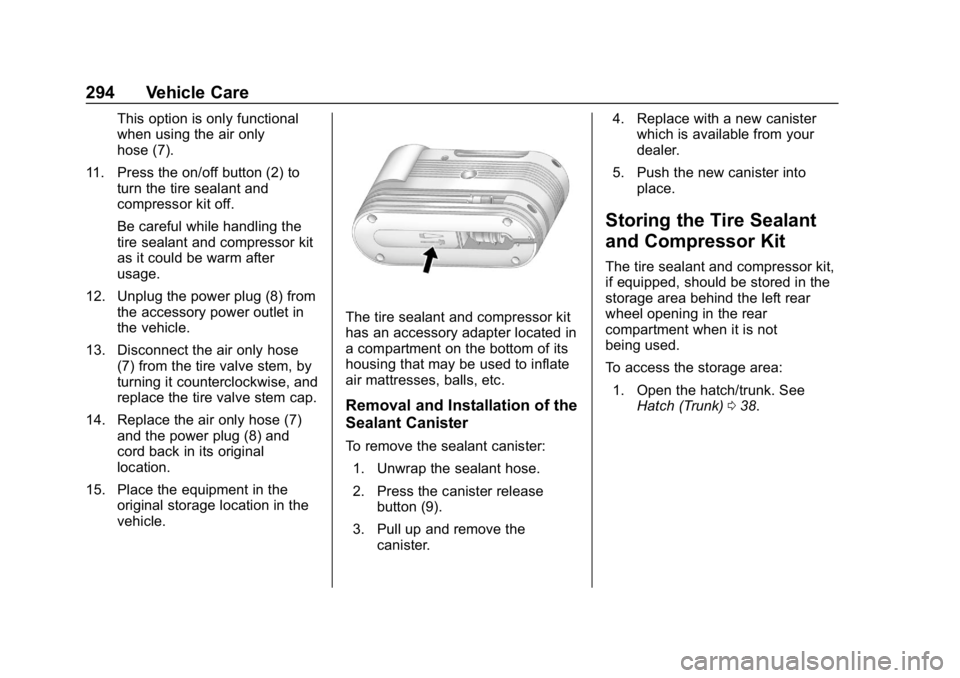
The tire sealant and compressor kit
has an accessory adapter located in
a compartment on the bottom of its
housing that may be used to inflate
air mattresses, balls, etc.
Removal and Installation of the
Sealant Canister
To remove the sealant canister:
1. Unwrap the sealant hose.
2. Press the canister release button (9).
3. Pull up and remove the canister. 4. Replace with a new canister
which is available from your
dealer.
5. Push the new canister into place.
Storing the Tire Sealant
and Compressor Kit
The tire sealant and compressor kit,
if equipped, should be stored in the
storage area behind the left rear
wheel opening in the rear
compartment when it is not
being used.
To access the storage area:
1. Open the hatch/trunk. See Hatch (Trunk) 038.