Page 73 of 114

Periodic maintenance an d a djustment
7-16
7
TIP
Be sure to wipe off spilled oil on any
parts after the engine and exhaust sys-
tem have cooled down.
NOTICE
ECA11621
In or der to prevent clutch slip-
pa ge (since the en gine oil also
lu bricates the clutch), do not
mix any chemical add itives. Do
not use oils with a d iesel speci-
fication of “CD” or oils of a hi gh-
er quality than specified . In
a ddition, do not use oils la bele d
“ENERGY CONSERVING II” or
hi gher.
Make sure that no forei gn mate-
rial enters the crankcase.
15. Check the filler cap O-ring for damage, and replace it if neces-
sary.
16. Install and tighten the oil filler cap.
17. Start the engine, and then let it idle for several minutes while checking
it for oil leakage. If oil is leaking,
immediately turn the engine off
and check for the cause.
TIP
After the engine is started, the engine
oil level warning light should go off if
the oil level is sufficient.
NOTICE
ECA10402
If the oil level warnin g li ght flickers
or remains on even if the oil level is
correct, imme diately turn the en gine
off an d have a Yamaha dealer check
the vehicle.
18. Turn the engine off, and then check the oil level and correct it if
necessary.
19. Check the dipstick O-ring for damage, and replace it if neces-
sary.
20. Install the cowlings.
UBN6E1E0.book Page 16 Thursday, October 5, 2017 2:48 PM
Page 74 of 114

Periodic maintenance an d a djustment
7-17
7
EAUS1203
Coolant
The coolant level should be checked
regularly. In addition, the coolant must
be changed at the intervals specified in
the periodic maintenance chart.
TIP
If genuine Yamaha coolant is not avail-
able, use an ethylene glycol antifreeze
containing corrosion inhibitors for alu-
minum engines and mix with distilled
water at a 1:1 ratio.
EAU3908BTo check the coolant level
Since the coolant level varies with en-
gine temperature, check when the en-
gine is cold.
1. Park the vehicle on a level surface.
2. With the vehicle in an upright posi- tion, look at the coolant level in the
reservoir. 3. If the coolant is at or below the mi-
nimum level mark, remove panel B
to access the coolant reservoir.
(See page 7-7.)
4. Remove the coolant reservoir cap. WARNING! Remove only the
coolant reservoir cap. Never at-
tempt to remove the ra diator
cap when the en gine is hot.
[EWA15162]
5. Add coolant to the maximum level
mark. NOTICE: If coolant is not
availa ble, use distille d water or
soft tap water instea d. Do not
use har d water or salt water
since it is harmful to the en gine.
If water has been used instead
of coolant, replace it with cool-
ant as soon as possi ble, other-
wise the coolin g system will not
b e protecte d a gainst frost an d
corrosion. If water has b een
a dde d to the coolant, have a
Yamaha dealer check the anti-
freeze content of the coolant as
soon as possi ble, otherwise the
effectiveness of the coolant will
b e red uced.
[ECA10473]
6. Install the coolant reservoir cap.
7. Install the panel.
Recommen ded coolant:
YAMALUBE coolant
Coolant quantity: Coolant reservoir (max level mark):0.25 L (0.26 US qt, 0.22 Imp.qt)
Radiator (including all routes): 2.30 L (2.43 US qt, 2.02 Imp.qt)
1. Coolant reservoir
2. Maximum level mark
3. Minimum level mark
2
1
3
1. Coolant reservoir cap
1
UBN6E1E0.book Page 17 Thursday, October 5, 2017 2:48 PM
Page 75 of 114
Periodic maintenance an d a djustment
7-18
7
EAU33032Chan gin g the coolant
The coolant must be changed at the in-
tervals specified in the periodic mainte-
nance and lubrication chart. Have a
Yamaha dealer change the coolant.
WARNING! Never attempt to remove the ra diator cap when the en gine is
hot.
[EWA10382] EAU36765
Air filter element
The air filter element must be replaced
at the intervals specified in the periodic
maintenance and lubrication chart.
Have a Yamaha dealer replace the air
filter element.
UBN6E1E0.book Page 18 Thursday, October 5, 2017 2:48 PM
Page 76 of 114
Periodic maintenance an d a djustment
7-19
7
EAU44735
Checkin g the en gine i dlin g
spee d
Check the engine idling speed and, if
necessary, have it corrected by a
Yamaha dealer.
EAU21386
Checkin g the throttle grip free
play
Measure the throttle grip free play as
shown.
Periodically check the throttle grip free
play and, if necessary, have a Yamaha
dealer adjust it.
En gine i dlin g spee d:
1250–1350 r/min
1. Throttle grip free play
Throttle g rip free play:
3.0–5.0 mm (0.12–0.20 in)
1
UBN6E1E0.book Page 19 Thursday, October 5, 2017 2:48 PM
Page 77 of 114

Periodic maintenance an d a djustment
7-20
7
EAU21403
Valve clearance
The valves are an important engine
component, and since valve clearance
changes with use, they must be
checked and adjusted at the intervals
specified in the periodic maintenance
chart. Unadjusted valves can result in
improper air-fuel mixture, engine
noise, and eventually engine damage.
To prevent this from occurring, have
your Yamaha dealer check and adjust
the valve clearance at regular intervals.
TIP
This service must be performed when
the engine is cold.
EAU70961
Tires
Tires are the only contact between the
vehicle and the road. Safety in all con-
ditions of riding depends on a relatively
small area of road contact. Therefore, it
is essential to maintain the tires in good
condition at all times and replace them
at the appropriate time with the speci-
fied tires.
Tire air pressure
The tire air pressure should be
checked and, if necessary, adjusted
before each ride.
WARNING
EWA18370
Operation of this vehicle with
improper tire air pressure may
cause severe injury or d eath
from loss of control.
The tire air pressure must b e
checked and a djuste d on col d
tires (i.e., when the temperature
of the tires equals the am bient
temperature).
WARNING
EWA10512
Never overloa d your vehicle. Opera-
tion of an overloa ded vehicle coul d
cause an acci dent.
Col d tire air pressure:
Front: 250 kPa (2.50 kgf/cm², 36 psi)
Rear:
290 kPa (2.90 kgf/cm², 42 psi)
Maximum loa d*:
185 kg (408 lb)
* Total weight of rider, passenger, car- go and accessories
UBN6E1E0.book Page 20 Thursday, October 5, 2017 2:48 PM
Page 78 of 114

Periodic maintenance an d a djustment
7-21
7 Tire inspection
The tires should be checked before
each ride. If the center tread depth
reaches the specified limit, if the tire
has a nail or glass fragments in it, or if
the sidewall is cracked, have a Yamaha
dealer replace the tire immediately.
TIP
The tire tread depth limits may differ
from country to country. Always com-
ply with the local regulations.
WARNING
EWA10472
Have a Yamaha dealer replace
excessively worn tires. Besi des
b ein g ille gal, operatin g the vehi-
cle with excessively worn tires
d ecreases ri din g sta bility an d
can lead to loss of control.
The replacement of all wheel
and b rake-relate d parts, inclu d-
in g the tires, shoul d b e left to a
Yamaha dealer, who has the
necessary professional knowl-
e dge an d experience to do so.
Ride at mo derate spee ds after
chan gin g a tire since the tire
surface must first b e “broken
in” for it to develop its optimal
characteristics.
Tire information
This model is equipped with tubeless
tires and tire air valves.
Tires age, even if they have not been
used or have only been used occasion-
ally. Cracking of the tread and sidewall
rubber, sometimes accompanied by
carcass deformation, is an evidence of
ageing. Old and aged tires should be
checked by tire specialists to ascertain
their suitability for further use.
WARNING
EWA10482
The front an d rear tires shoul d
b e of the same make an d d e-
si gn, otherwise the han dlin g
characteristics of the motorcy-
cle may b e different, which
coul d lea d to an acci dent.
Always make sure that the valve
caps are securely installe d to
prevent air pressure leakag e.
1. Tire sidewall
2. Tire tread depth
Minimum tire tread d epth (front an d
rear): 1.6 mm (0.06 in)
1. Tire air valve
2. Tire air valve core
3. Tire air valve cap with seal
UBN6E1E0.book Page 21 Thursday, October 5, 2017 2:48 PM
Page 79 of 114

Periodic maintenance an d a djustment
7-22
7
Use only the tire valves an d
valve cores liste d below to
avoi d tire d eflation during a
hi gh-spee d ri de.
After extensive tests, only the tires list-
ed below are approved for this model
by Yamaha.
WARNING
EWA10601
This motorcycle is fitte d with super-
hi gh-spee d tires. Note the followin g
points in or der to make the most ef-
ficient use of these tires. Use only the specified replace-
ment tires. Other tires may run
the dan ger of bursting at super
hi gh spee ds.
Bran d-new tires can have a rel-
atively poor g rip on certain roa d
surfaces until they have been
“ b roken in”. Therefore, it is a d-
visa ble before doin g any hi gh-
speed ridin g to ri de conserva-
tively for approximately 100 km
(60 mi) after installin g a new tire.
The tires must be warme d up
b efore a hi gh-spee d run.
Always a djust the tire air pres-
sure accor din g to the operating
con ditions.
Front tire:
Size:
120/70ZR17M/C (58W)
Manufacturer/model: DUNLOP/SPORTMAX D214F
BRIDGESTONE/BATTLAX S21F
Rear tire: Size:
180/55ZR17M/C(73W)
Manufacturer/model: DUNLOP/SPORTMAX D214
BRIDGESTONE/BATTLAX S21R
FRONT an d REAR:
Tire air valve:
TR412
Valve core: #9100 (original)
UBN6E1E0.book Page 22 Thursday, October 5, 2017 2:48 PM
Page 80 of 114

Periodic maintenance an d a djustment
7-23
7
EAU21963
Cast wheels
To maximize the performance, durabil-
ity, and safe operation of your vehicle,
note the following points regarding the
specified wheels.
The wheel rims should be
checked for cracks, bends, warp-
age or other damage before each
ride. If any damage is found, have
a Yamaha dealer replace the
wheel. Do not attempt even the
smallest repair to the wheel. A de-
formed or cracked wheel must be
replaced.
The wheel should be balanced
whenever either the tire or wheel
has been changed or replaced. An
unbalanced wheel can result in
poor performance, adverse han-
dling characteristics, and a short-
ened tire life.
EAU79960
Adjustin g the clutch lever free
play
Measure the clutch lever free play as
shown.
Periodically check the clutch lever free
play and, if necessary, adjust it as fol-
lows.
To increase the clutch lever free play,
turn the clutch lever free play adjusting
bolt at the clutch lever in direction (a).
To decrease the clutch lever free play,
turn the adjusting bolt in direction (b).
TIP
If the specified clutch lever free play
cannot be obtained as described
above, proceed as follows.
1. Fully turn the adjusting bolt at the
clutch lever in direction (a) to loos-
en the clutch cable.
2. Remove panel B and cowling C. (See page 7-7.)
3. Loosen the locknut at the crank- case.
1. Clutch lever free play
2. Clutch lever free play adjusting bolt
Clutch lever free play:10.0–15.0 mm (0.39–0.59 in)
12
(a)
(b)
UBN6E1E0.book Page 23 Thursday, October 5, 2017 2:48 PM
 1
1 2
2 3
3 4
4 5
5 6
6 7
7 8
8 9
9 10
10 11
11 12
12 13
13 14
14 15
15 16
16 17
17 18
18 19
19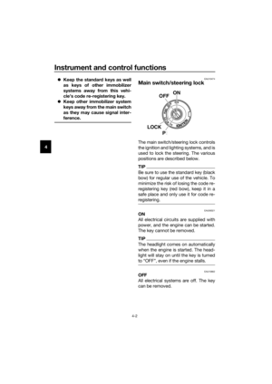 20
20 21
21 22
22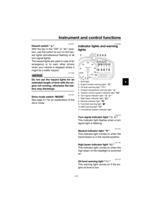 23
23 24
24 25
25 26
26 27
27 28
28 29
29 30
30 31
31 32
32 33
33 34
34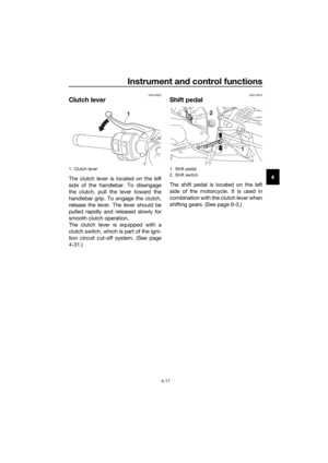 35
35 36
36 37
37 38
38 39
39 40
40 41
41 42
42 43
43 44
44 45
45 46
46 47
47 48
48 49
49 50
50 51
51 52
52 53
53 54
54 55
55 56
56 57
57 58
58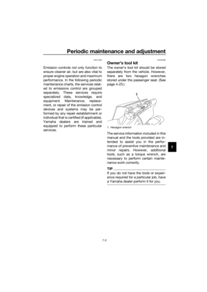 59
59 60
60 61
61 62
62 63
63 64
64 65
65 66
66 67
67 68
68 69
69 70
70 71
71 72
72 73
73 74
74 75
75 76
76 77
77 78
78 79
79 80
80 81
81 82
82 83
83 84
84 85
85 86
86 87
87 88
88 89
89 90
90 91
91 92
92 93
93 94
94 95
95 96
96 97
97 98
98 99
99 100
100 101
101 102
102 103
103 104
104 105
105 106
106 107
107 108
108 109
109 110
110 111
111 112
112 113
113
