Page 73 of 114

Periodic maintenance and adjustment
7-10
7
TIP
Skip steps 5–9 if the oil filter element is
not being replaced.
5. Remove the oil filter element cover
by removing the bolts.
6. Remove the oil filter element and
O-ring.
7. Check the O-ring for damage and
replace it if necessary.
8. Install the new oil filter element
and an O-ring.
9. Install the oil filter element cover
by installing the bolts, then tight-
ening them to the specified
torque.TIP
Make sure that the O-ring is properly
seated.
10. Install the washer and the engine
oil drain bolt, and then tighten the
drain bolt to the specified torque.
TIP
Make sure that the washer is properly
seated.
11. Refill with the specified amount of
the recommended engine oil, and
then install and tighten the oil filler
cap.
TIP
Be sure to wipe off spilled oil on any
parts after the engine and exhaust sys-
tem have cooled down.
NOTICE
ECA11671
Do not use oils with a diesel
specification of “CD” or oils of a
higher quality than specified. In
1. Oil filter element cover
1. Oil filter element
2. O-ring
3. Oil filter element cover
ZAUM11201
1
2
3
ZAUM0712
Tightening torque:
Oil filter cover bolt:
10 N·m (1.0 kgf·m, 7.4 lb·ft)
Tightening torque:
Engine oil drain bolt:
20 N·m (2.0 kgf·m, 15 lb·ft)
Recommended engine oil:
See page 9-1.
Oil change quantity:
Without oil filter element replace-
ment:
1.40 L (1.48 US qt, 1.23 Imp.qt)
With oil filter removal:
1.50 L (1.59 US qt, 1.32 Imp.qt)
UBL2E0E0.book Page 10 Friday, June 23, 2017 9:30 AM
Page 74 of 114

Periodic maintenance and adjustment
7-11
7addition, do not use oils labeled
“ENERGY CONSERVING II” or
higher.
Be sure no foreign material en-
ters the crankcase.
12. Start the engine, and then let it idle
for several minutes while checking
it for oil leakage. If oil is leaking,
immediately turn the engine off
and check for the cause.
13. Turn the engine off, and then
check the oil level and correct it if
necessary.
14. Reset the oil change indicator.
(See page 4-7.)
EAU20067
Final transmission oil
The final transmission case must be
checked for oil leakage before each
ride. If any leakage is found, have a
Yamaha dealer check and repair the
scooter. In addition, the final transmis-
sion oil must be changed as follows at
the intervals specified in the periodic
maintenance and lubrication chart.
1. Start the engine, warm up the final
transmission oil by riding the
scooter for several minutes, and
then stop the engine.
2. Place the scooter on the center-
stand.
3. Place an oil pan under the final
transmission case to collect the
used oil.
4. Remove the final transmission oil
filler cap and its O-ring from the fi-
nal transmission case.
5. Remove the final transmission oil
drain bolt and its gasket to drain
the oil from the final transmission
case.
1. Final transmission oil filler cap
2. O-ring
ZAUM1123
UBL2E0E0.book Page 11 Friday, June 23, 2017 9:30 AM
Page 75 of 114

Periodic maintenance and adjustment
7-12
7 6. Install the final transmission oil
drain bolt and its new gasket, and
then tighten the bolt to the speci-
fied torque.
7. Refill with the specified amount of
the recommended final transmis-
sion oil. WARNING! Make sure
that no foreign material enters
the final transmission case.
Make sure that no oil gets on
the tire or wheel.
[EWA11312]
8. Install the final transmission oil fill-
er cap and its new O-ring, and
then tighten the oil filler cap.
9. Check the final transmission case
for oil leakage. If oil is leaking,
check for the cause.
EAU20071
Coolant
The coolant level should be checked
before each ride. In addition, the cool-
ant must be changed at the intervals
specified in the periodic maintenance
and lubrication chart.
EAU78580To check the coolant level
1. Place the vehicle on the center-
stand.
TIP
The coolant level must be
checked on a cold engine since
the level varies with engine tem-
perature.
Make sure that the vehicle is posi-
tioned straight up when checking
the coolant level. A slight tilt to the
side can result in a false reading.
2. Check the coolant level through
the check window.
TIP
The coolant should be between the
minimum and maximum level marks.
1. Final transmission oil drain bolt
Tightening torque:
Final transmission oil drain bolt:
20 N·m (2.0 kgf·m, 15 lb·ft)
Recommended final transmission
oil:
See page 9-1.
Oil quantity:
0.21 L (0.22 US qt, 0.18 Imp.qt)
ZAUM07031
1. Coolant level check window
2. Maximum level mark
3. Minimum level mark
1
2
3
UBL2E0E0.book Page 12 Friday, June 23, 2017 9:30 AM
Page 76 of 114

Periodic maintenance and adjustment
7-13
73. If the coolant is at or below the
minimum level mark, remove the
left floorboard mat by pulling it up.
4. Remove the coolant reservoir cov-
er.
5. Remove the coolant reservoir cap,
add coolant to the maximum level
mark, and then install the reservoir
cap. WARNING! Remove only
the coolant reservoir cap. Never
attempt to remove the radiator
cap when the engine is hot.
[EWA15162] NOTICE: If coolant is not
available, use distilled water or
soft tap water instead. Do not
use hard water or salt water
since it is harmful to the engine.
If water has been used instead
of coolant, replace it with cool-
ant as soon as possible, other-
wise the cooling system will notbe protected against frost and
corrosion. If water has been
added to the coolant, have a
Yamaha dealer check the anti-
freeze content of the coolant as
soon as possible, otherwise the
effectiveness of the coolant will
be reduced.
[ECA10473]
6. Install the coolant reservoir cover.
7. Place the left floorboard mat in the
original position and push it down-
ward to secure it.
EAU33032Changing the coolant
The coolant must be changed at the in-
tervals specified in the periodic mainte-
nance and lubrication chart. Have a
Yamaha dealer change the coolant.
WARNING! Never attempt to remove
the radiator cap when the engine is
hot.
[EWA10382]
1. Floorboard mat
1. Coolant reservoir cover
1
1
1. Coolant reservoir cap
Coolant reservoir capacity (up to
the maximum level mark):
0.18 L (0.19 US qt, 0.16 Imp.qt)
1
UBL2E0E0.book Page 13 Friday, June 23, 2017 9:30 AM
Page 77 of 114

Periodic maintenance and adjustment
7-14
7
EAUM3370
Air filter and V-belt case air fil-
ter elements and check hoses
The air filter element should be re-
placed and the V-belt case air filter el-
ement should be cleaned at the
intervals specified in the periodic main-
tenance and lubrication chart. Service
the air filter elements more frequently if
you are riding in unusually wet or dusty
areas.
Replacing the air filter element
1. Place the scooter on the center-
stand.
2. Remove the air filter case cover by
removing the screws.
3. Pull the air filter element out.
4. Insert a new air filter element into
the air filter case.
5. Install the air filter case cover by
installing the screws.
To clean the air filter check hoses
1. Check the hoses at the bottom of
air filter case for accumulated dirt
or water.Left
2. If dirt or water is visible, remove
the hose, clean it, and then install
it.
Cleaning the V-belt case air filter el-
ement
1. Remove the V-belt case air filter
covers by removing the screws.
2. Remove the air filter element, and
then blow out the dirt with com-
pressed air as shown.
1. Air filter case cover
2. Screw
3. Air filter element
ZAUM1124
1
22
3
1. Air filter check hose
1. V-belt case air filter cover
2. Screw
ZAUM1126
1
ZAUM1125
UBL2E0E0.book Page 14 Friday, June 23, 2017 9:30 AM
Page 78 of 114
Periodic maintenance and adjustment
7-15
73. Check the air filter element for
damage and replace it if neces-
sary.
4. Install the air filter element with the
colored side facing outward.
5. Install the V-belt case air filter cov-
ers by installing the screws.
NOTICE: Make sure that each
filter element is properly seated
in its case. The engine should
never be operated without the
filter elements installed, other-
wise the piston(s) and/or cylin-
der(s) may become excessively
worn.
[ECA10532]EAU21386
Checking the throttle grip free
play
Measure the throttle grip free play as
shown.
Periodically check the throttle grip free
play and, if necessary, have a Yamaha
dealer adjust it.
1. V-belt case air filter element
1
ZAUM0706
1. Throttle grip free play
Throttle grip free play:
3.0–5.0 mm (0.12–0.20 in)
UBL2E0E0.book Page 15 Friday, June 23, 2017 9:30 AM
Page 79 of 114

Periodic maintenance and adjustment
7-16
7
EAU21402
Valve clearance
The valve clearance changes with use,
resulting in improper air-fuel mixture
and/or engine noise. To prevent this
from occurring, the valve clearance
must be adjusted by a Yamaha dealer
at the intervals specified in the periodic
maintenance and lubrication chart.
EAU69760
Tires
Tires are the only contact between the
vehicle and the road. Safety in all con-
ditions of riding depends on a relatively
small area of road contact. Therefore, it
is essential to maintain the tires in good
condition at all times and replace them
at the appropriate time with the speci-
fied tires.
Tire air pressure
The tire air pressure should be
checked and, if necessary, adjusted
before each ride.
WARNING
EWA10504
Operation of this vehicle with im-
proper tire pressure may cause se-
vere injury or death from loss of
control.
The tire air pressure must be
checked and adjusted on cold
tires (i.e., when the temperature
of the tires equals the ambient
temperature).
The tire air pressure must be
adjusted in accordance with the
riding speed and with the total
weight of rider, passenger, car-
go, and accessories approved
for this model.
UBL2E0E0.book Page 16 Friday, June 23, 2017 9:30 AM
Page 80 of 114

Periodic maintenance and adjustment
7-17
7
WARNING
EWA10512
Never overload your vehicle. Opera-
tion of an overloaded vehicle could
cause an accident.
Tire inspection
The tires must be checked before each
ride. If the center tread depth reaches
the specified limit, if the tire has a nail
or glass fragments in it, or if the side-
wall is cracked, have a Yamaha dealer
replace the tire immediately.
TIP
The tire tread depth limits may differ
from country to country. Always com-
ply with the local regulations.
WARNING
EWA10472
Have a Yamaha dealer replace
excessively worn tires. Besides
being illegal, operating the vehi-
cle with excessively worn tires
decreases riding stability and
can lead to loss of control.
The replacement of all wheel
and brake-related parts, includ-
ing the tires, should be left to a
Yamaha dealer, who has the
necessary professional knowl-
edge and experience to do so.
Ride at moderate speeds after
changing a tire since the tire
surface must first be “broken
in” for it to develop its optimal
characteristics.
Tire information
This model is equipped with tubeless
tires and rubber tire air valves.
Tires age, even if they have not been
used or have only been used occasion-
ally. Cracking of the tread and sidewall
rubber, sometimes accompanied by
carcass deformation, is an evidence of
ageing. Old and aged tires shall be
checked by tire specialists to ascertain
their suitability for further use.
Tire air pressure (measured on cold
tires):
1 person:
Front:
190 kPa (1.90 kgf/cm², 28 psi)
Rear:
220 kPa (2.20 kgf/cm², 32 psi)
2 persons:
Front:
210 kPa (2.10 kgf/cm², 30 psi)
Rear:
250 kPa (2.50 kgf/cm², 36 psi)
Maximum load*:
184 kg (406 lb)
* Total weight of rider, passenger, car-
go and accessories
1. Tire sidewall
2. Tire tread depth
12
Minimum tire tread depth (front and
rear):
1.6 mm (0.06 in)
UBL2E0E0.book Page 17 Friday, June 23, 2017 9:30 AM
 1
1 2
2 3
3 4
4 5
5 6
6 7
7 8
8 9
9 10
10 11
11 12
12 13
13 14
14 15
15 16
16 17
17 18
18 19
19 20
20 21
21 22
22 23
23 24
24 25
25 26
26 27
27 28
28 29
29 30
30 31
31 32
32 33
33 34
34 35
35 36
36 37
37 38
38 39
39 40
40 41
41 42
42 43
43 44
44 45
45 46
46 47
47 48
48 49
49 50
50 51
51 52
52 53
53 54
54 55
55 56
56 57
57 58
58 59
59 60
60 61
61 62
62 63
63 64
64 65
65 66
66 67
67 68
68 69
69 70
70 71
71 72
72 73
73 74
74 75
75 76
76 77
77 78
78 79
79 80
80 81
81 82
82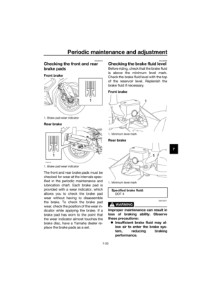 83
83 84
84 85
85 86
86 87
87 88
88 89
89 90
90 91
91 92
92 93
93 94
94 95
95 96
96 97
97 98
98 99
99 100
100 101
101 102
102 103
103 104
104 105
105 106
106 107
107 108
108 109
109 110
110 111
111 112
112 113
113