Page 25 of 96
Instrument and control functions
3-11
3 15 seconds. “OIL SERV” message and
the oil change tripmeter will also be re-
set.
Low battery indicator “ ”
This indicator flashes (“LOW BATT”
message will also appear) when the
battery voltage is under 10 volts.
TIP
If the low battery indicator comes on,
check and recharge the battery as nec-
essary. (See page 6-31.)
Warning and service messages
This function works in conjunction with
fuel meter, coolant temperature meter,
oil change indicator, and low battery
indicator by displaying a correspond-
ing warning or service message. When
two or more messages occur, push the“INFO” button to switch between and
check all messages in the following or-
der:
HIGH TEMP →LOW FUEL →LOW
BATT →OIL SERV
Lo
Hi
ZAUM1313
Lo
Hi
ZAUM1315
UBR3E1E0.book Page 11 Wednesday, August 10, 2016 9:45 AM
Page 26 of 96

Instrument and control functions
3-12
3
EAU1234K
Handlebar switches
Left
Right
EAU12352Pass switch “ ”
Press this switch to flash the headlight.
TIP
When the dimmer switch is set
to “ ”, the passing switch has no ef-
fect.
EAU12401Dimmer switch “ / ”
Set this switch to “ ” for the high
beam and to “ ” for the low beam.
EAU12461Turn signal switch “ / ”
To signal a right-hand turn, push this
switch to “ ”. To signal a left-hand
turn, push this switch to “ ”. When
released, the switch returns to the cen-
ter position. To cancel the turn signal
lights, push the switch in after it has re-
turned to the center position.
EAU12501Horn switch “ ”
Press this switch to sound the horn.
EAU12662Engine stop switch “ / ”
Set this switch to “ ” before starting
the engine. Set this switch to “ ” to
stop the engine in case of an emergen-
cy, such as when the vehicle overturns
or when the throttle cable is stuck.
EAU12713Start switch “ ”
Push this switch to crank the engine
with the starter. See page 5-2 for start-
ing instructions prior to starting the en-
gine.
EAU42342The engine trouble warning light and
ABS warning light may come on when
the key is turned to “ON” and the start
switch is pushed, but this does not in-
dicate a malfunction.
EAUM3451Info switch “INFO”
This switch is used to perform selec-
tions in the function display of the
multi-function meter unit and to acti-
vate or deactive the high-rpm warning
light. (See page 3-4 for information on
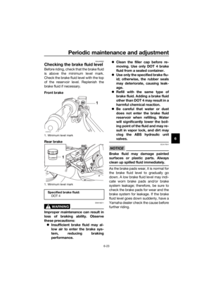
1. Pass switch “ ”
2. Dimmer switch “ / ”
3. Turn signal switch “ / ”
4. Horn switch “ ”
1. Engine stop switch “ / ”
2. Start switch “ ”
3. “INFO” switch
ZAUM1162
ZAUM1163
13
2I NFO
UBR3E1E0.book Page 12 Wednesday, August 10, 2016 10:09 AM
Page 27 of 96
Instrument and control functions
3-13
3
the multi-function meter unit and page
3-3 for information on the tachometer
high-rpm warning light.)
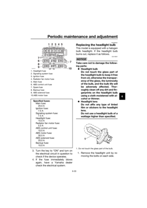
EAU12822
Clutch lever
The clutch lever is located on the left
side of the handlebar. To disengage
the clutch, pull the lever toward the
handlebar grip. To engage the clutch,
release the lever. The lever should be
pulled rapidly and released slowly for
smooth clutch operation.
The clutch lever is equipped with a
clutch switch, which is part of the igni-
tion circuit cut-off system. (See page
3-20.)
1. Clutch lever
1
UBR3E1E0.book Page 13 Wednesday, August 10, 2016 10:09 AM
Page 28 of 96
Instrument and control functions
3-14
3
EAU12872
Shift pedal
The shift pedal is located on the left
side of the motorcycle and is used in
combination with the clutch lever when
shifting the gears of the 6-speed con-
stant-mesh transmission equipped on
this motorcycle.
EAU12892
Brake lever
The brake lever is located on the right
side of the handlebar. To apply the
front brake, pull the lever toward the
throttle grip.
1. Shift pedal
ZAUM1200
1. Brake lever
ZAUM1201
1
I
NFO
UBR3E1E0.book Page 14 Wednesday, August 10, 2016 9:45 AM
Page 29 of 96

Instrument and control functions
3-15
3
EAU12944
Brake pedal
The brake pedal is located on the right
side of the motorcycle. To apply the
rear brake, press down on the brake
pedal.
EAU63040
ABS
The Yamaha ABS (Anti-lock Brake
System) features a dual electronic con-
trol system, which acts on the front and
rear brakes independently.
Operate the brakes with ABS as you
would conventional brakes. If the ABS
is activated, a pulsating sensation may
be felt at the brake lever or brake ped-
al. In this situation, continue to apply
the brakes and let the ABS work; do
not “pump” the brakes as this will re-
duce braking effectiveness.
WARNING
EWA16051
Always keep a sufficient distance
from the vehicle ahead to match the
riding speed even with ABS.
The ABS performs best with
long braking distances.
On certain surfaces, such as
rough or gravel roads, the brak-
ing distance may be longer with
the ABS than without.
The ABS is monitored by an ECU,
which will revert the system to conven-
tional braking if a malfunction occurs.
TIP
The ABS performs a self-diagno-
sis test each time the vehicle first
starts off after the key is turned to
“ON” and the vehicle has traveled
at a speed of 10 km/h (6 mi/h) or
higher. During this test, a “click-
ing” noise can be heard from the
hydraulic control unit, and if the
brake lever or brake pedal is even
slightly applied, a vibration can be
felt at the lever and pedal, but
these do not indicate a malfunc-
tion.
1. Brake pedal
ZAUM1202
UBR3E1E0.book Page 15 Wednesday, August 10, 2016 9:45 AM
Page 30 of 96

Instrument and control functions
3-16
3This ABS has a test mode which
allows the owner to experience
the pulsation at the brake lever or
brake pedal when the ABS is op-
erating. However, special tools are
required, so please consult your
Yamaha dealer.
NOTICE
ECA20100
Be careful not to damage the wheel
sensor or wheel sensor rotor; other-
wise, improper performance of the
ABS will result.
EAUM2082
Fuel tank cap
To remove the fuel tank cap
1. Open the fuel tank cap lock cover.
2. Insert the key into the lock and
turn it 1/4 turn counterclockwise.
The lock will be released and the
fuel tank cap can be removed.
To install the fuel tank cap
1. Push the fuel tank cap into posi-
tion with the key inserted in the
lock.
2. Turn the key clockwise to the orig-
inal position, and then remove it.
3. Close the lock cover.
TIP
The fuel tank cap cannot be installed
unless the key is in the lock. In addi-
tion, the key cannot be removed if the
cap is not properly installed and
locked.
WARNING
EWA11142
Make sure that the fuel tank cap is
properly installed before riding.
Leaking fuel is a fire hazard.
1. Front wheel sensor rotor
2. Front wheel sensor
1. Rear wheel sensor rotor
2. Rear wheel sensor
ZAUM1227
1
2
ZAUM1228
1
2
1. Fuel tank cap lock cover
2. Unlock.
UBR3E1E0.book Page 16 Wednesday, August 10, 2016 9:45 AM
Page 31 of 96

Instrument and control functions
3-17
3
EAU13213
Fuel
Make sure there is sufficient gasoline in
the tank.
WARNING
EWA10882
Gasoline and gasoline vapors are
extremely flammable. To avoid fires
and explosions and to reduce the
risk of injury when refueling, follow
these instructions.
1. Before refueling, turn off the en-
gine and be sure that no one is sit-
ting on the vehicle. Never refuel
while smoking, or while in the vi-
cinity of sparks, open flames, or
other sources of ignition such as
the pilot lights of water heaters
and clothes dryers.
2. Do not overfill the fuel tank. Stop
filling when the fuel reaches the
bottom of the filler tube. Because
fuel expands when it heats up,
heat from the engine or the sun
can cause fuel to spill out of the
fuel tank.
3. Wipe up any spilled fuel immedi-
ately. NOTICE: Immediately
wipe off spilled fuel with a clean,dry, soft cloth, since fuel may
deteriorate painted surfaces or
plastic parts.
[ECA10072]
4. Be sure to securely close the fuel
tank cap.
WARNING
EWA15152
Gasoline is poisonous and can
cause injury or death. Handle gaso-
line with care. Never siphon gasoline
by mouth. If you should swallow
some gasoline or inhale a lot of gas-
oline vapor, or get some gasoline in
your eyes, see your doctor immedi-
ately. If gasoline spills on your skin,
wash with soap and water. If gaso-
line spills on your clothing, change
your clothes.
EAU75320
NOTICE
ECA11401
Use only unleaded gasoline. The use
of leaded gasoline will cause severe
damage to internal engine parts,
such as the valves and piston rings,
as well as to the exhaust system.
1. Fuel tank filler tube
2. Maximum fuel level
Recommended fuel:
Premium unleaded gasoline (Gaso-
hol [E10] acceptable)
Fuel tank capacity:
11.5 L (3.04 US gal, 2.53 Imp.gal)
Fuel reserve amount (when the fuel
level warning light comes on):
3.0 L (0.79 US gal, 0.66 Imp.gal)
UBR3E1E0.book Page 17 Wednesday, August 10, 2016 9:45 AM
Page 32 of 96
.
Check that gasoline nozzle has
the same iden")
Instrument and control functions
3-18
3TIP
This mark identifies the recom-
mended fuel for this vehicle as
specified by European regulation
(EN228).
Check that gasoline nozzle has
the same identifier when fueling.
Your Yamaha engine has been de-
signed to use premium unleaded gas-
oline with a research octane number of
95 or higher. If knocking (or pinging)
occurs, use a gasoline of a different
brand. Use of unleaded fuel will extend
spark plug life and reduce mainte-
nance costs.
Gasohol
There are two types of gasohol: gaso-
hol containing ethanol and that con-
taining methanol. Gasohol containing
ethanol can be used if the ethanol con-
tent does not exceed 10% (E10). Gas-
ohol containing methanol is not
recommended by Yamaha because it
can cause damage to the fuel system
or vehicle performance problems.
EAU13434
Catalytic converter
This model is equipped with a catalytic
converter in the exhaust system.
WARNING
EWA10863
The exhaust system is hot after op-
eration. To prevent a fire hazard or
burns:
Do not park the vehicle near
possible fire hazards such as
grass or other materials that
easily burn.
Park the vehicle in a place
where pedestrians or children
are not likely to touch the hot
exhaust system.
Make sure that the exhaust sys-
tem has cooled down before
doing any maintenance work.
Do not allow the engine to idle
more than a few minutes. Long
idling can cause a build-up of
heat.
NOTICE
ECA10702
Use only unleaded gasoline. The use
of leaded gasoline will cause unre-
pairable damage to the catalytic
converter.
E5E10
UBR3E2E0.book Page 18 Friday, May 11, 2018 11:08 AM


EAU12822
Clutch lever
The clutch lever is located on the l")
