Page 97 of 108

Motorcycle care and storage
8-3
1
2
3
4
5
6
789
10
11
12
After cleaning
1. Dry the motorcycle with a chamois or an absorbing cloth.
2. Immediately dry the drive chain and lubricate it to prevent it from
rusting.
3. Use a chrome polish to shine chrome, aluminum and stain-
less-steel parts.
4. To prevent corrosion, it is recom- mended to apply a corrosion pro-
tection spray on all metal,
including chrome- and nickel-plat-
ed, surfaces.
5. Use spray oil as a universal clean- er to remove any remaining dirt.
6. Touch up minor paint damage caused by stones, etc.
7. Wax all painted surfaces.
8. Let the motorcycle dry completely before storing or covering it.
WARNING
EWA11132
Contaminants on the brakes or tires
can cause loss of control.
Make sure that there is no oil or
wax on the brakes or tires.
If necessary, clean the brake
discs and brake linings with a regular brake disc cleaner or ac-
etone, and wash the tires with
warm water and a mild deter-
gent. Before riding at higher
speeds, test the motorcycle’s
braking performance and cor-
nering behavior.
NOTICE
ECA10801
Apply spray oil and wax spar-
ingly and make sure to wipe off
any excess.
Never apply oil or wax to any
rubber and plastic parts, but
treat them with a suitable care
product.
Avoid using abrasive polishing
compounds as they will wearaway the paint.
TIP
Consult a Yamaha dealer for ad-
vice on what products to use.
Washing, rainy weather or humid
climates can cause the headlight
lens to fog. Turning the headlight
on for a short period of time will
help remove the moisture from the
lens.
B67-9-E2.book 3 ページ 2018年6月5日 火曜日 午前9時7分
Page 98 of 108

Motorcycle care and storage
8-4
1
2
3
4
5
6
78
9
10
11
12
EAU26183
StorageShort-term
Always store your motorcycle in a cool,
dry place and, if necessary, protect it
against dust with a porous cover. Be
sure the engine and the exhaust sys-
tem are cool before covering the motor-
cycle.NOTICE
ECA10811
Storing the motorcycle in a
poorly ventilated room or cover-
ing it with a tarp, while it is still
wet, will allow water and humid-
ity to seep in and cause rust.
To prevent corrosion, avoid
damp cellars, stables (because
of the presence of ammonia)
and areas where strong chemi-cals are stored.
Long-term
Before storing your motorcycle for sev-
eral months: 1. Follow all the instructions in the “Care” section of this chapter. 2. Fill up the fuel tank and add fuel
stabilizer (if available) to prevent
the fuel tank from rusting and the
fuel from deteriorating.
3. Perform the following steps to pro- tect the cylinders, piston rings, etc.
from corrosion.
a. Remove the spark plug caps and spark plugs.
b. Pour a teaspoonful of engine oil into each spark plug bore.
c. Install the spark plug caps onto the spark plugs, and then place
the spark plugs on the cylinder
head so that the electrodes are
grounded. (This will limit spark-
ing during the next step.)
d. Turn the engine over several times with the starter. (This will
coat the cylinder walls with oil.)
WARNING! To prevent dam-
age or injury from sparking,
make sure to ground the
spark plug electrodes while
turning the engine
over.
[EWA10952]
e. Remove the spark plug capsfrom the spark plugs, and then
install the spark plugs and the spark plug caps.
4. Lubricate all control cables and the pivoting points of all levers and
pedals as well as of the sidestand/
centerstand.
5. Check and, if necessary, correct the tire air pressure, and then lift
the motorcycle so that both of its
wheels are off the ground. Alterna-
tively, turn the wheels a little every
month in order to prevent the tires
from becoming degraded in one
spot.
6. Cover the muffler outlet with a plastic bag to prevent moisture
from entering it.
7. Remove the battery and fully charge it. Store it in a cool, dry
place and charge it once a month.
Do not store the battery in an ex-
cessively cold or warm place [less
than 0 C (30 F) or more than 30
C (90 F)]. For more information
on storing the battery, see page
7-29.
TIPMake any necessary repairs beforestoring the motorcycle.
B67-9-E2.book 4 ページ 2018年6月5日 火曜日 午前9時7分
Page 99 of 108

Overall width: 800 mm (31.5 in)
Overall height: 1110 mm (43.7 in)
Seat height:
825 mm (32.5 in)
Wheelba")
9-1
1
2
3
4
5
6
7
8910
11
12
Specifications
EAU70621
Dimensions:Overall length:2095 mm (82.5 in)
Overall width: 800 mm (31.5 in)
Overall height: 1110 mm (43.7 in)
Seat height:
825 mm (32.5 in)
Wheelbase: 1400 mm (55.1 in)
Ground clearance: 130 mm (5.12 in)
Minimum turning radius:
3.3 m (10.83 ft)Weight:Curb weight:210 kg (463 lb)Engine:Combustion cycle:4-stroke
Cooling system: Liquid cooled
Valve train:
DOHC
Cylinder arrangement: Inline
Number of cylinders: 4-cylinder
Displacement:
998 cm
3
Bore stroke:
79.0 50.9 mm (3.11 2.00 in) Compression ratio:
12.0 : 1
Starting system:
Electric starter
Lubrication system: Wet sump
Engine oil:Recommended brand:
YAMALUBE
Type: Full synthetic
SAE viscosity grades: 10W-40
Recommended engine oil grade:
API service SG type or higher, JASO stan-
dard MA
Engine oil quantity:
Oil change:3.90 L (4.12 US qt, 3.43 Imp.qt)
With oil filter removal:
4.10 L (4.33 US qt, 3.61 Imp.qt)Coolant quantity:Coolant reservoir (up to the maximum level
mark): 0.25 L (0.26 US qt, 0.22 Imp.qt)
Radiator (including all routes): 2.25 L (2.38 US qt, 1.98 Imp.qt)Air filter:Air filter element:Oil-coated paper elementFuel:Recommended fuel:
Premium unleaded gasoline (Gasohol
[E10] acceptable) Fuel tank capacity:
17 L (4.5 US gal, 3.7 Imp.gal)
Fuel reserve amount:
4.0 L (1.06 US gal, 0.88 Imp.gal)
Fuel injection:Throttle body:ID mark:B671 00Spark plug(s):Manufacturer/model:
NGK/LMAR9E-J
Spark plug gap: 0.6–0.7 mm (0.024–0.028 in)Clutch:Clutch type:
Wet, multiple-discDrivetrain:Primary reduction ratio:1.634 (67/41)
Final drive:
Chain
Secondary reduction ratio: 2.688 (43/16)
Transmission type: Constant mesh 6-speed
Gear ratio:
1st:2.600 (39/15)
2nd:
2.176 (37/17)
3rd: 1.842 (35/19)
4th: 1.579 (30/19)
B67-9-E2.book 1 ページ 2018年6月5日 火曜日 午前9時7分
Page 100 of 108

6th:
1.250 (30/24)
Chassis:Frame type: Diamond
Caster angle:
24.0
Trail: 102 mm (4.0 in)Front tire:Type:
Tubeless
Size: 120/70ZR17M")
Specifications
9-2
1
2
3
4
5
6
7
89
10
11
12
5th: 1.381 (29/21)
6th:
1.250 (30/24)
Chassis:Frame type: Diamond
Caster angle:
24.0
Trail: 102 mm (4.0 in)Front tire:Type:
Tubeless
Size: 120/70ZR17M/C(58W)
Manufacturer/model: BRIDGESTONE/BATTLAX HYPERS-
PORT S20FRear tire:Type:Tubeless
Size: 190/55ZR17M/C(75W)
Manufacturer/model: BRIDGESTONE/BATTLAX HYPERS-
PORT S20RLoading:Maximum load:170 kg (375 lb)
* (Total weight of rider, passenger, cargo and accessories)
Tire air pressure (measured on cold-
tires):1 person:Front:
250 kPa (2.50 kgf/cm
2, 36 psi)
Rear: 290 kPa (2.90 kgf/cm2, 42 psi)
2 persons: Front: 250 kPa (2.50 kgf/cm2, 36 psi)
Rear: 290 kPa (2.90 kgf/cm2, 42 psi)
Front wheel:Wheel type:Cast wheel
Rim size: 17M/C x MT3.50Rear wheel:Wheel type:Cast wheel
Rim size: 17M/C x MT6.00Front brake:Type:Hydraulic dual disc brake
Specified brake fluid: DOT 4Rear brake:Type:Hydraulic single disc brake
Specified brake fluid: DOT 4
Front suspension:Type:Telescopic fork
Spring: Coil spring
Shock absorber: Hydraulic damper
Wheel travel:
120 mm (4.7 in)Rear suspension:Type:Swingarm (link suspension)
Spring:
Coil spring
Shock absorber: Gas-hydraulic damper
Wheel travel: 120 mm (4.7 in)Electrical system:System voltage:12 V
Ignition system: TCI
Charging system:
AC magnetoBattery:Model:YTZ10S
Voltage, capacity:
12 V, 8.6 Ah (10 HR)Bulb wattage:Headlight:LED
B67-9-E2.book 2 ページ 2018年6月5日 火曜日 午前9時7分
Page 101 of 108

Specifications
9-3
1
2
3
4
5
6
7
8910
11
12
Brake/tail light:LED
Front turn signal light:
LED
Rear turn signal light: LED
Auxiliary light: LED
License plate light:
LED
Meter lighting: LED
Neutral indicator light: LED
High beam indicator light:
LED
Oil pressure warning light: LED
Turn signal indicator light: LED
Coolant temperature warning light:
LED
Engine trouble warning light: LED
Steering damper warning light: LED
ABS warning light:
LED
Cruise control “SET” indicator light: LED
Cruise control “ON” indicator light: LED
Immobilizer system indicator light:
LED Shift timing indicator light:
LED
Traction control system indicator light:
LED
Fuse(s):Main fuse:50.0 A
Terminal fuse 1:
2.0 A
Headlight fuse: 10.0 A
Brake light fuse: 1.0 A
Signaling system fuse:
7.5 A
Ignition fuse: 15.0 A
Radiator fan motor fuse: 15.0 A
Sub radiator fan motor fuse:
10.0 A
Hazard fuse: 7.5 A
ABS ECU fuse: 7.5 A
Fuel injection system fuse:
15.0 A
ABS motor fuse: 30.0 A
ABS solenoid fuse: 10.0 A
Cruise control fuse:
1.0 A Backup fuse:
7.5 A
Electronic throttle valve fuse:
7.5 A
B67-9-E2.book 3 ページ 2018年6月5日 火曜日 午前9時7分
Page 102 of 108
10-1
1
2
3
4
5
6
7
8
910
11
12
Consumer information
EAU53562
Identification numbersRecord the vehicle identification num-
ber, engine serial number, and the
model label information in the spaces
provided below. These identification
numbers are needed when registering
the vehicle with the authorities in your
area and when ordering spare parts
from a Yamaha dealer.
VEHICLE IDENTIFICATION NUM-
BER:
ENGINE SERIAL NUMBER:
MODEL LABEL INFORMATION:
EAU26401
Vehicle identification number
The vehicle identification number is
stamped into the steering head pipe.
Record this number in the space pro-
vided.TIPThe vehicle identification number is
used to identify your motorcycle and
may be used to register your motorcy-
cle with the licensing authority in yourarea.
EAU26442
Engine serial number
The engine serial number is stamped
into the crankcase.
1. Vehicle identification number
1
1. Engine serial number
1
B67-9-E2.book 1 ページ 2018年6月5日 火曜日 午前9時7分
Page 103 of 108
 Re-
cord the information on this label in the
space pro")
Consumer information
10-2
1
2
3
4
5
6
7
8
91011
12
EAU26481
Model label
The model label is affixed to the frame
under the seat. (See page 4-22.) Re-
cord the information on this label in the
space provided. This information will be
needed when ordering spare parts from
a Yamaha dealer.
EAU69910
Diagnostic connectorThe diagnostic connector is located as
shown.
EAU74702
Vehicle data recordingThis model’s ECU stores certain vehi-
cle data to assist in the diagnosis of
malfunctions and for research and de-
velopment purposes. This data will be
uploaded only when a special Yamaha
diagnostic tool is attached to the vehi-
cle, such as when maintenance checks
or service procedures are performed.
Although the sensors and recorded
data will vary by model, the main data
points are:
Vehicle status and engine perfor-
mance data
Fuel-injection and emission-relat-
ed data
Yamaha will not disclose this data to a
third party except:
With the consent of the vehicle
owner
Where obligated by law
For use by Yamaha in litigation
For general Yamaha-conducted
research purposes when the data
is not related to an individual vehi-
cle nor owner
1. Model label
1
1. Diagnostic connector
1
B67-9-E2.book 2 ページ 2018年6月5日 火曜日 午前9時7分
Page 104 of 108

11-1
1
2
3
4
5
6
7
8
9
1011
12
IndexAABS ....................................................... 4-18
ABS warning light.................................... 4-6
Air filter element .................................... 7-15
Auxiliary DC jack ................................... 4-28BBattery................................................... 7-29
Brake and clutch levers, checking and lubricating .................................... 7-26
Brake and shift pedals, checking
and lubricating .................................... 7-25
Brake fluid, changing ............................ 7-22
Brake fluid level, checking .................... 7-21
Brake lever ............................................ 4-17
Brake lever free play, checking ............. 7-20
Brake light switches .............................. 7-20
Brake pedal ........................................... 4-17CCables, checking and lubricating .......... 7-25
Canister................................................. 7-10
Care ........................................................ 8-1
Catalytic converter ................................ 4-21
Clutch lever ........................................... 4-16
Clutch lever free play, adjusting ............ 7-19
Coolant.................................................. 7-14
Coolant temperature warning light .......... 4-6
Cruise control indicator lights .................. 4-5
Cruise control switches ........................... 4-4
Cruise control system ............................. 3-1DData recording, vehicle ......................... 10-2
Diagnostic connector ............................ 10-2
Dimmer/Pass switch ............................... 4-4
D-mode (drive mode) .............................. 3-3 Drive chain, cleaning and lubricating .... 7-24
Drive chain slack .................................. 7-23
Drive mode switch .................................. 4-4
EEngine break-in ...................................... 6-3
Engine idling speed, checking .............. 7-15
Engine oil .............................................. 7-10
Engine serial number............................ 10-1
Engine trouble warning light ................... 4-6
EXUP system ....................................... 4-27FFront and rear brake
pads, checking .... 7-21
Front fork, adjusting .............................. 4-23
Front fork, checking .............................. 7-27
Fuel....................................................... 4-19
Fuel consumption, tips for reducing........ 6-3
Fuel tank cap ........................................ 4-19
Fuel tank overflow hose........................ 4-21
Fuses, replacing ................................... 7-30HHandlebar switches ................................ 4-3
Hazard switch ......................................... 4-4
High beam indicator light ........................ 4-5
Horn switch ............................................. 4-4IIdentification numbers .......................... 10-1
Ignition circuit cut-off system ................ 4-29
Immobilizer system ................................. 4-1
Immobilizer system indicator light........... 4-7
Indicator lights and warning lights .......... 4-5LLuggage strap holders .......................... 4-27MMain switch/steering lock........................ 4-2 Maintenance and lubrication, periodic..... 7-5
Maintenance, emission control
system .................................................. 7-3
Matte color, caution ................................. 8-1
Model label ............................................ 10-2
Multi-function meter unit .......................... 4-8
NNeutral indicator light .............................. 4-5OOil pressure warning light........................ 4-5PParking .................................................... 6-4
Part locations .......................................... 2-1QQuick shift system ................................... 3-6SSafety information ................................... 1-1
Seat ....................................................... 4-22
SELECT switch ....................................... 4-4
Shift indicator light ................................... 4-7
Shifting .................................................... 6-2
Shift pedal ............................................. 4-16
Shock absorber assembly, adjusting .... 4-24
Sidestand .............................................. 4-28
Sidestand, checking an d lubricating...... 7-27
Spark plugs, checking ............................. 7-9
Special features ...................................... 3-1
Specifications .......................................... 9-1
Starting the engine .................................. 6-1
Steering, checking................................. 7-28
Steering damper warning light ................ 4-7
Stop/Run/Start switch.............................. 4-4
Storage.................................................... 8-4
Supporting the motorcycle .................... 7-33
B67-9-E2.book 1 ページ 2018年6月5日 火曜日 午前9時7分
 1
1 2
2 3
3 4
4 5
5 6
6 7
7 8
8 9
9 10
10 11
11 12
12 13
13 14
14 15
15 16
16 17
17 18
18 19
19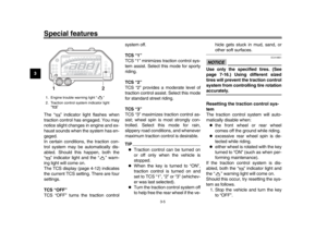 20
20 21
21 22
22 23
23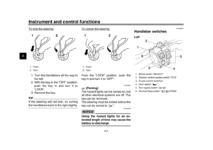 24
24 25
25 26
26 27
27 28
28 29
29 30
30 31
31 32
32 33
33 34
34 35
35 36
36 37
37 38
38 39
39 40
40 41
41 42
42 43
43 44
44 45
45 46
46 47
47 48
48 49
49 50
50 51
51 52
52 53
53 54
54 55
55 56
56 57
57 58
58 59
59 60
60 61
61 62
62 63
63 64
64 65
65 66
66 67
67 68
68 69
69 70
70 71
71 72
72 73
73 74
74 75
75 76
76 77
77 78
78 79
79 80
80 81
81 82
82 83
83 84
84 85
85 86
86 87
87 88
88 89
89 90
90 91
91 92
92 93
93 94
94 95
95 96
96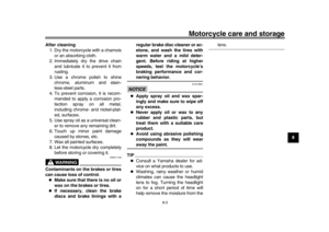 97
97 98
98 99
99 100
100 101
101 102
102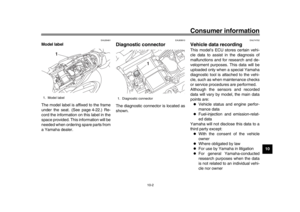 103
103 104
104 105
105 106
106 107
107