Page 33 of 100

Instrument and control functions
3-18
3
Gasohol
There are two types of gasohol: gaso-
hol containing ethanol and that con-
taining methanol. Gasohol containing
ethanol can be used if the ethanol con-
tent does not exceed 10% (E10). Gas-
ohol containing methanol is not
recommended by Yamaha because it
can cause damage to the fuel system
or vehicle performance problems.
EAU76871
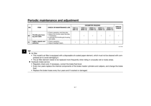
Fuel tank overflow hoseTIPSee page 6-9 for breather hose infor-
mation.Before operating the motorcycle:
Check the fuel tank overflow hose
connection.
Check the fuel tank overflow hose
for cracks or damage, and replace
it if necessary.
Make sure that the end of the fuel
tank overflow hose is not blocked,
and clean it if necessary.
Make sure that the fuel tank over-
flow hose is routed through the
clamp.
Make sure that the paint mark on
the fuel tank overflow hose is be-
low the clamp.1. Fuel tank overflow hose
2. Clamp
3. Original position (paint mark)
12
3
UB4CE0E0.book Page 18 Monday, December 11, 2017 3:53 PM
Page 34 of 100

Instrument and control functions
3-19
3
EAU13434
Catalytic converterThis model is equipped with a catalytic
converter in the exhaust system.
WARNING
EWA10863
The exhaust system is hot after op-
eration. To prevent a fire hazar d or
b urns:
Do not park the vehicle near
possi ble fire hazard s such as
g rass or other materials that
easily burn.
Park the vehicle in a place
where ped estrians or chil dren
are not likely to touch the hot
exhaust system.
Make sure that the exhaust sys-
tem has cooled down before
d oin g any maintenance work.
Do not allow the en gine to i dle
more than a few minutes. Lon g
i d lin g can cause a b uild-up of
heat.
NOTICE
ECA10702
Use only unlea ded g asoline. The use
of lead ed g asoline will cause unre-
pairab le dama ge to the catalytic
converter.
EAU83850
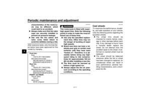
SeatsPassen ger seat
To remove the passenger seat1. Insert the key into the seat lock, and then turn it counterclockwise.
2. While holding the key in that posi- tion, lift the rear of the passenger
seat and pull it backward.1. Seat lock
2. Unlock.
2
1
UB4CE0E0.book Page 19 Monday, December 11, 2017 3:53 PM
Page 35 of 100

Instrument and control functions
3-20
3
To install the passenger seat
1. Insert the projections on the front
of the passenger seat into the seat
holders as shown, and then push
the rear of the seat down to lock it
in place.
2. Remove the key.
Ri der seat
To remove the rider seat1. Remove the passenger seat, and then remove the hexagon wrench
located on the bottom of the seat. 2. Remove the bolts with the hexa-
gon wrench.
3. Lift the seat rearward and up to re- move it. To install the rider seat
1. Fit the slot in the seat onto the pro-
jection on the frame cross mem-
ber as shown, and then place the
seat in the original position.
2. Install the bolts with the hexagon wrench.
3. Insert the hexagon wrench back into its holder on the passenger
seat.
4. Install the passenger seat.TIPMake sure that the seats are properly
secured before riding.
1. Projection
2. Seat holder
1
2
1. Passenger seat
2. Hexagon wrench
1. Bolt
1
2
1
1. Slot
2. Projection
1
2
UB4CE0E0.book Page 20 Monday, December 11, 2017 3:53 PM
Page 36 of 100

Instrument and control functions
3-21
3
EAU59981
Helmet hol din g ca bleA helmet holding cable is located on
the bottom of the passenger seat. Use
this cable in conjunction with the
screwdriver to secure a helmet to the
vehicle.
To secure a helmet with the helmet
hol din g cab le
1. Remove the passenger seat. (See page 3-19.)
2. Remove the screwdriver from its holders on the passenger seat,
and then remove the helmet hold-
ing cable from the screwdriver.
TIPWhen removing the screwdriver, slide
the screwdriver toward the “ ” mark
on the passenger seat.3. Pass the helmet holding cablethrough the buckle on the helmet
strap.
4. Hook the cable loops over the screwdriver, install the screw-
driver by first inserting the screw-
driver into the holder with the “ ”
mark, and then slide the screw-
driver toward the holder with
the “ ” mark.
TIPMake sure that the screwdriver is se-
curely positioned between its holders,
and then position the cable loops to-
ward the middle of the screwdriver be-
fore installing the passenger seat.5. Install the passenger seat.WARNING! Never ri de with a
helmet attached to the helmet
hol der, since the helmet may hit
o bjects, causin g loss of control
an d possi bly an acci dent.
[EWA10162]
1. Passenger seat
2. Helmet holding cable
3. Screwdriver1
2
3
1. Screwdriver
2. “ ” mark
3. “ ” mark
1
2
3
1. Helmet
2. Helmet holding cable
3. Screwdriver
4. Holder
1
2
3
4
UB4CE0E0.book Page 21 Monday, December 11, 2017 3:53 PM
Page 37 of 100

Instrument and control functions
3-22
3
To release a helmet from the helmet
hol
din g cab le
1. Remove the passenger seat.
2. Remove the screwdriver, then re- move the helmet holding cable
from the helmet.
3. Store the cable under the seat by hooking the cable loops over the
screwdriver, install the screw-
driver in its original position, and
then hook the helmet holding ca-
ble over the hook on the bottom of
the passenger seat.
4. Install the passenger seat.
EAU83880
Stora ge compartmentThe storage compartment is located as
shown. When storing documents, wrap them
in a plastic bag so they will not get wet.
When washing the vehicle, avoid
spraying water directly under the seat.
WARNING
EWA10962
Do not exceed the load limit of
1.5 k g (3 l b) for the stora ge com-
partment.
Do not excee d the maximum
loa d of 172 k g (379 l b) for the ve-
hicle.
1. Screwdriver
2. Helmet holding cable
3. Hook1
2
3
1. Storage compartment cover
1. Storage compartment
11
UB4CE0E0.book Page 22 Monday, December 11, 2017 3:53 PM
Page 38 of 100

Instrument and control functions
3-23
3
EAU57941
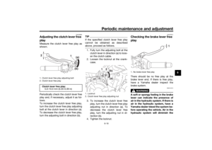
A djustin g the shock a bsorb er
assem blyThis shock absorber assembly is
equipped with a spring preload adjust-
ing ring and a rebound damping force
adjusting screw.NOTICE
ECA10102
To avoi d d amag ing the mechanism,
d o not attempt to turn b eyond the
maximum or minimum setting s.Spring preloa d
To increase the spring preload and
thereby harden the suspension, turn
the adjusting ring in direction (a). To
decrease the spring preload and there-
by soften the suspension, turn the ad-
justing ring in direction (b).
Align the appropriate notch in the
adjusting ring with the position in-
dicator on the shock absorber.
Use the special wrench and the
extension bar included in the own-
er’s tool kit to make the adjust-
ment. Re
boun d d ampin g force
To increase the rebound damping
force and thereby harden the rebound
damping, turn the adjusting screw in
direction (a). To decrease the rebound
damping force and thereby soften the
rebound damping, turn the adjusting
screw in direction (b).
1. Extension bar
2. Special wrench
3. Spring preload adjusting ring
4. Position indicatorSprin g preloa d setting :
Minimum (soft): 1
Standard: 4
Maximum (hard):
7
76
54321
3
(b)(a)
2
1
4
1. Rebound damping force adjusting screwRe
boun d d ampin g setting :
Minimum (soft): 3 turn(s) in direction (b)*
Standard: 1.5 turn(s) in direction (b)*
Maximum (hard):
0 turn(s) in direction (b)*
* With the adjusting screw fully turned in direction (a)
1 (a)(b)
UB4CE0E0.book Page 23 Monday, December 11, 2017 3:53 PM
Page 39 of 100

Instrument and control functions
3-24
3
TIPTo obtain a precise adjustment, it is
advisable to check the actual total
number of turns of the damping force
adjusting mechanism. This adjustment
range may not exactly match the spec-
ifications listed due to small differenc-
es in production.
WARNING
EWA10222
This shock a bsor ber assem bly con-
tains hig hly pressurize d nitro gen
g as. Rea d an d un derstan d the fol-
lowin g information before han dlin g
the shock ab sorber assem bly.
Do not tamper with or attempt
to open the cylin der assem bly.
Do not su bject the shock a b-
sor ber assem bly to an open
flame or other hi gh heat source.
This may cause the unit to ex-
plod e due to excessive gas
pressure.
Do not d eform or damag e the
cylin der in any way. Cylin der
d amag e will result in poor
d ampin g performance.
Do not dispose of a damag ed or
worn-out shock a bsor ber
as-
sem bly yourself. Take the shock
a b sor ber assem bly to a Yamaha
d ealer for any service.
EAU38963
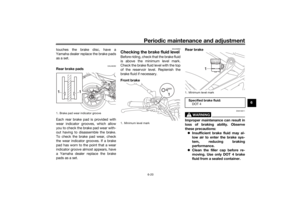
Lu gga ge strap hol dersThere are six luggage strap holders,
four on the bottom of the passenger
seat and one on each passenger foot-
rest. To use the luggage strap holders1. Luggage strap holder
2. Hook
1. Luggage strap holder
12
2
11
UB4CE0E0.book Page 24 Monday, December 11, 2017 3:53 PM
Page 40 of 100
 Un-
hook the straps from the hooks, and
then install the seat with the straps
hanging out fro")
Instrument and control functions
3-25
3 on the passenger seat, remove the
passenger seat. (See page 3-19.) Un-
hook the straps from the hooks, and
then install the seat with the straps
hanging out from under the passenger
seat.
EAU70641
Auxiliary DC connectorThis vehicle is equipped with an auxil-
iary DC connector. Consult your
Yamaha dealer before installing any accessories.
EAU15306
Si destan dThe sidestand is located on the left
side of the frame. Raise the sidestand
or lower it with your foot while holding
the vehicle upright.TIPThe built-in sidestand switch is part of
the ignition circuit cut-off system,
which cuts the ignition in certain situa-
tions. (See the following section for an
explanation of the ignition circuit cut-
off system.)
WARNING
EWA10242
The vehicle must not be ri dden with
the si destan d d own, or if the si de-
stan d cannot b e properly moved up
(or does not stay up), otherwise the
si destan d coul d contact the groun d
an d d istract the operator, resultin g
in a possi ble loss of control.
Yamaha’s i gnition circuit cut-off
system has been desi gne d to assist
the operator in fulfillin g the respon-
si bility of raisin g the si destan d b e-
fore startin g off. Therefore, check
UB4CE0E0.book Page 25 Monday, December 11, 2017 3:53 PM