2018 VOLVO XC90 T8 control module
[x] Cancel search: control modulePage 37 of 686

YOUR VOLVO
35
Important information onaccessories and extra equipment
Incorrectly connected or installed accessories or extra equipment may have an adverse effect onthe vehicle's electronics.
We strongly recommend that Volvo owners use only genuine, Volvo-approved accessories, andthat accessory installations be performed only bya trained and qualified Volvo service technician.Certain accessories only work when the associ-ated software is installed in the vehicle's com-puter system. The equipment described in the Owner's Manual is not available in all vehicles. Vehicles may beequipped differently depending on marketrequirements and national or local laws and regu-lations. Optional or accessory equipment may not be available in all countries or markets. Please notethat some vehicles may be equipped differently,depending on special legal requirements. Formore information on which equipment is standardand which is an option or accessory, please con-tact your Volvo retailer.
NOTE
Do not export your Volvo to another country before investigating that country's applicablesafety and exhaust emission requirements. Insome cases it may be difficult or impossibleto comply with these requirements. Modifica-tions to the emission control system(s) mayrender your Volvo not certifiable for legaloperation in the U.S., Canada and other coun-tries.
WARNING
CALIFORNIA proposition 65 Engine exhaust, some of its constituents, and certain vehicle components contain or emitchemicals known to the state of California tocause cancer, and birth defects or otherreproductive harm. In addition, certain fluidscontained in vehicles and certain products ofcomponent wear contain or emit chemicalsknown to the State of California to cause can-cer, and birth defects or other reproductiveharm.
WARNING
Certain of the vehicle's components, such as airbag modules, seat belt tensioners, adjusta-ble steering wheel columns and button cellbatteries, may contain perchlorate materials.Special handling may apply for service or vehi-cle end of life disposal. See www.dtsc.ca.gov/hazardouswaste/ perchlorate.
WARNING
The driver is always responsible for operating the vehicle in a safe manner and for comply-ing with current statutes and regulations. It is also essential to maintain and service the vehicle according to Volvo's recommendationsas stated in the owner's information and theservice and warranty booklet. If the on-board information differs from the printed owner's manual, the printed informa-tion always takes precedence.
Related information
• Accessory installation (p. 36)
• Connecting equipment to the vehicle's data link connector (p. 36)
• Using the Owner's Manual (p. 21)
Page 444 of 686
STARTING AND DRIVING
* Option/accessory.
442
Shiftlock The automatic transmission's shiftlock function helps prevent inadvertently moving the gearselector between different positions.
Automatic shiftlockThe automatic shiftlock has a separate safety system.
From Park - P
To move the gear selector from the P position,
the brake pedal must be depressed and the igni- tion in mode II.
From Neutral - N
If the gear selector is in N and the vehicle has
been stationary for at least 3 seconds (with or without the engine running), the gear selector willbe locked in that position. To move the gear selector from N to another
gear, the brake pedal must be depressed and the ignition in mode II.
Messages in the instrument panelIf the gear selector is locked in position, a mes- sage will appear in the instrument panel, e.g.
Gear lever Press brake pedal to activate
gear lever.
There is no mechanical shiftlock function.
Related information
• Gear selector positions for automatic trans- missions (p. 439)
The kickdown function
Kickdown is used when maximum acceleration is needed, e.g. when passing.
When the accelerator pedal is depressed all the way to the floor (past the normal full acceleratorposition), the transmission will automaticallyengage kickdown, i.e. immediately shift down to alower gear. If the accelerator pedal is released from the kick- down position, the transmission will automaticallyshift up again.
Safety function
The transmission control module is equipped with a downshift protection feature to help prevent theengine from overheating. In some conditions, the transmission will prevent downshifting/kickdown if this would lead to suchhigh engine speed (rpm) that the engine couldbe damaged. If the driver still attempts downshift-ing or kickdown at a high rpm, nothing will hap-pen and the original gear will remain selected. With kickdown, the vehicle can downshift one or more steps at a time depending on the enginespeed. The vehicle upshifts when the engine rea-ches its maximum rpm to prevent engine dam-age.
Related information
• Gear selector positions for automatic trans-missions (p. 439)
Gear indicator
*
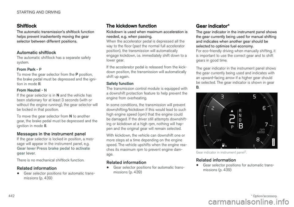
The gear indicator in the instrument panel shows the gear currently being used for manual shiftingand indicates when another gear should beselected to optimize fuel economy.
For eco-friendly driving when manually shifting, it is important to use the correct gear and to shiftgears in good time. The gear indicator in the instrument panel shows the gear currently being used and indicates withan upward-facing arrow if a higher gear shouldbe selected. The gear indicator is shown in gear B .
Gear indicator in instrument panel 2
.
Related information
• Gear selector positions for automatic trans- missions (p. 439)
Page 469 of 686

STARTING AND DRIVING
467
WARNING
Carbon monoxide is a poisonous, colorless, and odorless gas. It is present in all exhaustgases. If you ever smell exhaust fumes insidethe vehicle, make sure the passenger com-partment is ventilated, and immediately returnthe vehicle to a trained and qualified Volvoservice technician for correction.
Demanding drivingIn demanding driving conditions, e.g. when driving in a hot climates, driving with a trailer or drivingfor longer periods at higher altitudes (mountainlandscapes) than normal, it is recommended switching to a higher octane fuel than AKI 916
or
changing gasoline brand to take full advantage of your car's engine capacity and obtain the opti-mum driving force.
Related information
• Fuel (p. 464)
• Emission controls (p. 467)
Emission controls
Three-way catalytic converter
•Keep your engine properly tuned. Certain engine malfunctions, particularly involving theelectrical, fuel or distributor ignition systems,may cause unusually high three-way catalyticconverter temperatures. Do not continue tooperate your vehicle if you detect enginemisfire, noticeable loss of power or otherunusual operating conditions, such as engineoverheating or backfiring. A properly tunedengine will help avoid malfunctions thatcould damage the three-way catalytic con-verter.
• Do not park your vehicle over combustiblematerials, such as grass or leaves, which cancome into contact with the hot exhaust sys-tem and cause such materials to ignite undercertain wind and weather conditions.
• Excessive starter cranking (in excess of oneminute), or an intermittently firing or floodedengine can cause three-way catalytic con-verter or exhaust system overheating.
• Remember that tampering or unauthorizedmodifications to the engine, the Engine Con-trol Module, or the vehicle may be illegal andcan cause three-way catalytic converter orexhaust system overheating. This includes:altering fuel injection settings or compo-nents, altering emission system components or location or removing components, and/orrepeated use of leaded fuel.NOTE
Unleaded fuel is required for vehicles with three-way catalytic converters.
Heated oxygen sensorsThe heated oxygen sensors monitor the oxygen content of the exhaust gases. Readings are fedinto a control module that continuously monitorsengine functions and controls fuel injection. Theratio of fuel to air into the engine is continuouslyadjusted for efficient combustion to help reduceharmful emissions.
Related information
•
Octane rating (p. 465)
• Fuel (p. 464)
6
AKI (Anti Knock Index) is an average value of RON (Research Octane Number) and MON (Motor Octane Number) - (RON)+(MON)/2
Page 625 of 686

MAINTENANCE AND SERVICE
}}
623
Fuse pliers are provided on the inside of the fuse box cover to assist in removing and insertingfuses. There are also spaces for several extra fuses in the fusebox.
PositionsThere is a decal with a diagram of the locationsof the fuses on the inside of the cover.
• Fuses 1–13, 18–30, 35–37 and 46–70 are"Micro" fuses.
• Fuses 14–17, 31–34, 38–45 and 71–78 are"MCase" fuses and should only be replaced by a workshop 17
.
FunctionAA
– –
– –
– –
Control module for actuator for engaging/changing gears, auto-matic transmission 5
High-voltage coolant heater control module
5
FunctionAA
Control module for A/C; heat exchanger cut-off valve; cut-offvalve for coolant through the cli-mate system5
Hybrid battery control module; high-voltage converter for com-bined high-voltage generator/starter motor with 500 V–12 Vvoltage converter5
– –
Converter for controlling feed to rear axle electric motor
10
Hybrid battery control module; high-voltage converter for com-bined high-voltage generator/starter motor with 500 V–12 Vvoltage converter10
Charge module 5
Cut-off valve for hybrid battery coolant; coolant pump 1 forhybrid battery
10
Coolant pump for electric drive system
10
FunctionAA
Hybrid component cooling fan 25
– –
– –
– –
– –
– –
– –
– –
– –
– –
12 V outlet in tunnel console, front15
12 V outlet in tunnel console between second-row seats
B
12 V outlet in tunnel console,between rear seats C
; USB ports
in tunnel console between rearseats C 15
17
An authorized Volvo workshop is recommended.
Page 626 of 686

||
MAINTENANCE AND SERVICE
* Option/accessory.
624
FunctionAA
12 V outlet in trunk/cargo com- partment *
USB ports for iPad holders C15
– –
– –
– –
– –
Heated windshield
*, left side Shunt
Heated windshield
*, left side 40
Headlight washers
*25
Windshield washer 25
– –
Horn 20
Alarm siren
* 5
Brake system control module (valves, parking brake) 40
Wipers 30
Rear window washer 25
FunctionAA
Heated windshield
*, right side 40
Parking heater
* 20
Brake system control module (ABS pump) 40
– –
Heated windshield
*, right side Shunt
Fed when ignition is on: Engine control module; transmissioncomponents, electrical powersteering, central electrical mod-ule 5
Exterior vehicle sound (certain markets)
5
Right-side headlight 7.5 Right-side headlight, some mod- els with LED
D 15
– –
– –
– –
Airbags 5
FunctionAA
Left-side headlight 7.5 Left-side headlight, some mod- els with LED
D 15
Accelerator pedal sensor 5
Transmission control module; gear selector control module 15
Engine control module 5
– –
– –
– –
– –
Engine control module; actuator; throttle unit; turbo-charger valve20
Solenoids; valve; engine cooling system thermostat10
Vacuum regulators; valve 7.5
Spoiler shutter control module; radiator shutter control module 5
– –
Page 627 of 686

MAINTENANCE AND SERVICE
625
FunctionAA
Heated oxygen sensor, front; heated oxygen sensor, rear15
Oil pump solenoid; A/C mag- netic coupling; heated oxygensensor (center)15
– –
Engine control module 20
Ignition coils; spark plugs 15
– –
– –
Transmission oil pump control module
30
Vacuum pump control module 40
Transmission actuator 25
– –
– –
– –
A
Ampere
B Not Excellence
C Excellence
D LED (Light Emitting Diode)
Related information
• Fuses and fuseboxes (p. 620)
• Replacing fuses (p. 621)
Page 629 of 686

MAINTENANCE AND SERVICE
}}
* Option/accessory.627
Fuse pliers are provided on the inside of the fuse box cover to assist in removing and insertingfuses. There are also spaces for several extra fuses in the
distribution box in the engine compart-
ment .
Positions
•Fuses 1, 3-21, 23-36, 39-53 and 55-59 are "Micro" fuses.
• Fuses 2-22, 37-38 and 54 are "MCase"fuses and should only be replaced by a work- shop 18
.
FunctionAA
– –
– –
– –
Movement sensor * 5
Media player 5
Instrument panel 5
Center console buttons 5
Sun sensor 5
FunctionAA
– –
– –
Steering wheel module 5
Module for start knob and parking brake controls 5
Heated steering wheel
* module 15
– –
– –
– –
– –
Climate system control module 10
– –
Data link connector OBD-II 10
Center display 5
Climate system blower module (front) 40
USB HUB 5
FunctionAA
Instrument lighting; Interior lighting; Rearview mirror auto-dim function
*;
Rain and light sensors *; Rear tun-
nel console keypad, second row of seats *B
; Power front seats *; Rear
door control panels; Climate sys- tem blower module left/right Power rear seats C
; Display for rear
seat convenience functions C
; Rear
seat massage function C7.5
Control module for driver support functions
5
Panoramic roof with sun curtain
*20
Head-up display
* 5
Passenger compartment lighting 5
– –
Ceiling console display (seat belt reminder/front passenger side air-bag indicator) 5
– –
Humidity sensor 5
18
An authorized Volvo workshop is recommended.
Page 630 of 686

||
MAINTENANCE AND SERVICE
* Option/accessory.
628
FunctionAA
Door module in right-side rear door 20
Fuses in the trunk/cargo compart- ment 10
Control module for Internet-con- nected vehicle; Control module forVolvo On Call 5
Door module in left-side rear door 20
Audio control module (amplifier) (certain models only)
40
Climate system blower module (rear)
* 40
Multi-band antenna module 5
Front seat massage function
*5
– –
Rear window wiper 15
Fuel pump control module 15
Relay windings for distribution box in engine compartment; Relaywindings for transmission oil pump 5
– –
FunctionAA
Driver's seat heating 15
Front passenger's seat heating 15
Coolant pump 10
– –
Door module in left-side front door 20
Active chassis control module
*20
– –
Sensus control module 10
– –
– –
Door module in right-side front door 20
Display for rear seat convenience functions
C
; On-board diagnostics
(OBD II) in tunnel console betweenrear seats C
; Extra movement sen-
sor C 5
C
FunctionAA
TV
* (certain markets only) 5
Primary fuse for fuses 53 and 58 15
A
Ampere
B Not Excellence
C Excellence
Related information
• Fuses and fuseboxes (p. 620)
• Replacing fuses (p. 621)