2018 VOLVO XC60 T8 tow
[x] Cancel search: towPage 381 of 674

DRIVER SUPPORT
}}
* Option/accessory.379
Side cameras
The side cameras119
are located in the rearview mirrors.
The side cameras can show views along each side of the vehicle.
Related information
• Park Assist Camera
* (p. 377)
Park Assist Camera trajectory lines
The Park Assist Camera uses trajectory lines and fields on the screen to indicate the vehicle'sposition in relation to its immediate surround-ings.
Example 120
of trajectory lines.
The trajectory lines show the anticipated trajec- tory for the vehicle's outermost dimensions basedon the current position of the steering wheel to help simplify parallel parking, backing into tightspaces or attaching a trailer. The lines on the screen are projected as if they were painted lines on the ground behind thevehicle and are directly affected by the way inwhich the steering wheel is turned. This enablesthe driver to see path the vehicle will take, even ifhe/she turns the steering wheel. These lines also indicate the outermost limits that any object (towbar, rearview mirrors, corners ofthe body, etc.) extends out from the vehicle.
NOTE
•
When reversing with a trailer that is not electrically connected to the vehicle, thescreen guide lines show the path the vehicle
will take – not the trailer.
• The screen does not show guide lines when a trailer is electrically connected tothe vehicle's electrical system.
• Guide lines are not shown when zoomingin.
119
Note: This illustration is general and details may vary depending on model.
120 The illustration is generic - details may vary according to vehicle model.
Page 382 of 674

||
DRIVER SUPPORT
* Option/accessory.
380
CAUTION
• Bear in mind that when the rearward camera view is selected, the screen onlyshows the area behind the vehicle – payattention to the sides and front of thevehicle when steering while reversing.
• The same applies to the reverse – payattention to what is happening with therear parts of the vehicle when the frontcamera view is selected.
• Note that the guide lines show the
short-
est path – pay extra attention to ensure
that the vehicle sides do not come incontact with/travel over anything whensteering while driving forward or that thevehicle front moves toward/over anythingwhen steering while reversing.
Trajectory lines in 360° view *
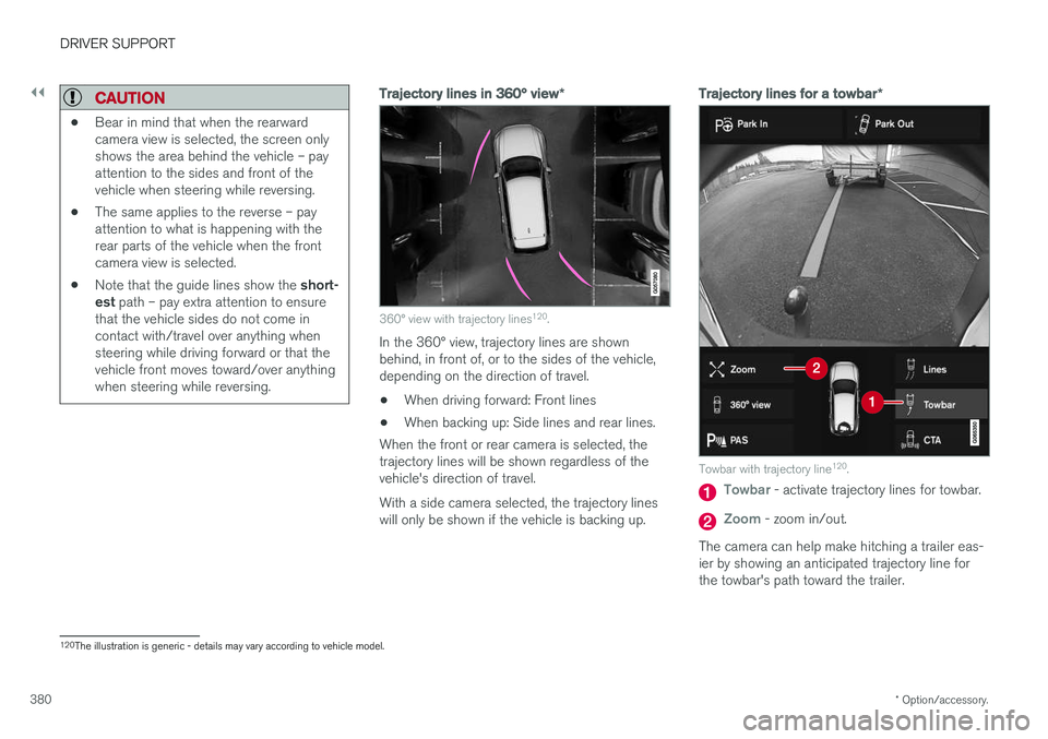
360° view with trajectory lines120
.
In the 360° view, trajectory lines are shown behind, in front of, or to the sides of the vehicle,depending on the direction of travel.
• When driving forward: Front lines
• When backing up: Side lines and rear lines.
When the front or rear camera is selected, thetrajectory lines will be shown regardless of thevehicle's direction of travel. With a side camera selected, the trajectory lines will only be shown if the vehicle is backing up.
Trajectory lines for a towbar *
Towbar with trajectory line120
.
Towbar - activate trajectory lines for towbar.
Zoom - zoom in/out.
The camera can help make hitching a trailer eas- ier by showing an anticipated trajectory line for the towbar's path toward the trailer.
120 The illustration is generic - details may vary according to vehicle model.
Page 383 of 674

DRIVER SUPPORT
* Option/accessory.381
1.
Tap
Towbar (1).
> The trajectory line for the towbar's antici- pated path toward the vehicle will appear and the vehicle's trajectory lines will dis-appear. Trajectory lines cannot be displayed for both the vehicle and the towbar at thesame time.
2. Tap
Zoom (2) for a close-up view for more
precise maneuvering.
> The camera will zoom in.
Related information
• Park Assist Camera
* (p. 377)
Sensor field from Park Assist forPark Assist Camera
If the vehicle is equipped with Park Assist, dis- tances will be shown in the 360° view with col-ored fields for each sensor that has detected anobstacle.
Front and rear sensors
The screen can display colored sensor fields on the vehicle symbol 121
.
The front and rear fields change colors (from yel- low to orange to red) as the vehicle moves closerto an obstacle.
Front and rear fieldcolorsDistance in meters(feet)
Yellow 0.6-1.5 (2.0-4.9)
Orange 0.4-0.6 (1.3-2.0)
Red 0-0.4 (0-1.3)
Side sensor fields
The side sensor fields will only be shown in orange.
Side field colorDistance in meters (feet)
Orange 0-0.3 (0-1.0)
Related information
• Park Assist Camera
* (p. 377)
121
The illustration is generic - details may vary according to vehicle model.
Page 393 of 674

DRIVER SUPPORT
}}
* Option/accessory.391
Park Assist Pilot * limitations
Park Assist Pilot PAP 126
may not be able to
detect all conditions in all situations and func- tionality may therefore be limited.WARNING
• The PAP function is supplementary driver support intended to facilitate driving andhelp make it safer – it cannot handle allsituations in all traffic, weather and roadconditions.
• Pay particular attention to people andanimals near the vehicle.
• Bear in mind that the front end of thevehicle may swing out towards oncomingtraffic during the parking maneuver.
• Objects situated higher than the detec-tion area of the sensors are not includedwhen the parking maneuver is calculated,which could cause PAP to swing into theparking space too early. Such parkingspaces should be avoided for this reason.
• PAP is not a substitute for the driver'sattention and judgment. The driver isalways responsible for ensuring the vehi-cle is driven in a safe manner, at theappropriate speed, with an appropriatedistance to other vehicles, and in accord-ance with current traffic rules and regula-tions.
The driver should be aware of the following limi-tations for Park Assist Pilot:
The parking sequence is cancelledA parking sequence will be cancelled if:
• the driver moves the steering wheel
• the vehicle's speed exceeds 7 km/h (4 mph)
• the driver taps
Cancel in the center display
• when the anti-lock brakes or the Electronic stability control are engaged - e.g. when awheel loses grip on a slippery road
• when the power steering works at reduced power - e.g. during cooling due to overheat- ing (see section "Speed-dependent steeringforce").
A message in the center display will explain whythe parking sequence was cancelled.
CAUTION
Under certain circumstances, PAP may not be able to find parking spaces – one reason maybe that the sensors are disrupted by externalsound sources that emit the same ultrasonicfrequencies that the system works with. Examples of such sources include horns, wet tires on asphalt, pneumatic brakes, exhaustnoise from motorcycles, etc.
126 Park Assist Pilot
Page 398 of 674

HYBRID INFORMATION
396
General information about TwinEngine
Twin Engine vehicles are driven just like any other vehicle, but certain functions differ from avehicle powered exclusively by gasoline. Theelectric motor powers the vehicle primarily at lowspeeds; the gasoline engine is used at higherspeeds or during more active driving.
The instrument panel displays Twin Engine-spe- cific information - charging information, selecteddrive mode, distance to discharged battery andhybrid battery charge level. Different drive modes can be selected while driv- ing, e.g. electric power only or, if more power isneeded, a combination of electric and gasolinepower. The vehicle calculates the optimal combi-nation of driveability, driving experience, environ-mental impact and fuel economy for the selecteddrive mode. In order to function optimally, the hybrid battery (and its electrical drive systems) and the gasolineengine (and its drive systems) must be at thecorrect operating temperature. Battery capacitycan be considerably reduced if the battery is toocold or too hot. Preconditioning prepares thevehicle's drive systems and passenger compart-ment before driving to help reduce both wear andenergy consumption. It also helps increase thehybrid battery's range. The hybrid battery, which powers the electric motor, is recharged using the charging cable. Itcan also be recharged during light braking and through engine braking in gear position
B. The
combustion engine can also help recharge thehybrid battery.
Important
No electrical current
Keep in mind that if there is no electrical current to the vehicle, i.e. the ignition is switched off orthe start battery is discharged, certain functionssuch as brakes, power steering, etc. will not work.
WARNING
If the vehicle does not have electrical current and both the electric motor and the gasolineengine are switched off, the brakes cannot beused to stop the vehicle.
Towing not permitted
Never tow a Twin Engine vehicle behind another vehicle, as this could damage the electric motor.
Exterior engine noise
WARNING
Keep in mind that the vehicle does not emit any engine noise when using the electricmotor and may therefore be difficult to detectfor children, pedestrians, cyclists or animals.This is especially true at low speeds, e.g. inparking lots.
High-voltage electrical current
WARNING
Several components in the vehicle work with high voltage that can be hazardous in case ofan incorrect procedure. These componentsand any orange wiring in the vehicle may onlybe handled by trained and qualified Volvoservice technicians.
Do not touch anything that is not clearly descri- bed in this Owner's Manual.
Related information
• Charging the hybrid battery (p. 397)
• Hybrid gauge (p. 83)
• Drive modes (p. 435)
• Starting and stopping preconditioning(p. 222)
• Hybrid battery (p. 609)
• Factors affecting electric motor range(p. 448)
• Gear selector positions for automatic trans-missions (p. 429)
• Towing using a towline (p. 466)
Page 410 of 674

HYBRID INFORMATION
* Option/accessory.
408
Stopping hybrid battery charging
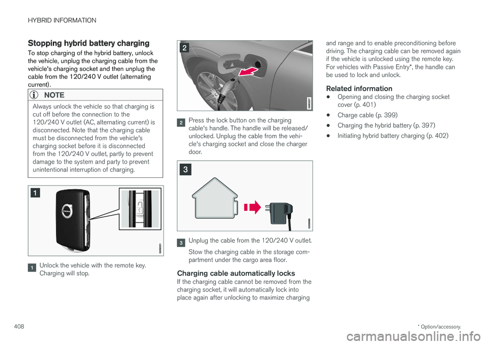
To stop charging of the hybrid battery, unlock the vehicle, unplug the charging cable from thevehicle's charging socket and then unplug thecable from the 120/240 V outlet (alternatingcurrent).
NOTE
Always unlock the vehicle so that charging is cut off before the connection to the120/240 V outlet (AC, alternating current) isdisconnected. Note that the charging cablemust be disconnected from the vehicle'scharging socket before it is disconnectedfrom the 120/240 V outlet, partly to preventdamage to the system and party to preventunintentional interruption of charging.
Unlock the vehicle with the remote key. Charging will stop.
Press the lock button on the charging cable's handle. The handle will be released/unlocked. Unplug the cable from the vehi-cle's charging socket and close the chargerdoor.
Unplug the cable from the 120/240 V outlet. Stow the charging cable in the storage com- partment under the cargo area floor.
Charging cable automatically locksIf the charging cable cannot be removed from thecharging socket, it will automatically lock intoplace again after unlocking to maximize charging and range and to enable preconditioning beforedriving. The charging cable can be removed againif the vehicle is unlocked using the remote key. For vehicles with Passive Entry
*, the handle can
be used to lock and unlock.
Related information
• Opening and closing the charging socket cover (p. 401)
• Charge cable (p. 399)
• Charging the hybrid battery (p. 397)
• Initiating hybrid battery charging (p. 402)
Page 422 of 674

||
STARTING AND DRIVING
420augment braking. This is indicated in the instru- ment panel with the pointer down in the red area.
Symbols in the instrument panel
SymbolMeaning
A
B
Check the brake fluid level. If the level is low, fill brake fluid andcheck to determine the reason forthe loss of brake fluid.
A
BFault in pedal sensor.
SymbolMeaning
A
BSteady glow for 2 seconds after the engine is started: Automaticfunction check. Steady glow for more than 2 sec- onds: Fault in the ABS system. Thevehicle's regular brake system isstill working, but without the ABSfunction.
If the message Brake pedal Cha-
racteristics changed Service required
is displayed, the "Brake-
by-wire" system is not functioning properly. The brake pedal will godown further than normal andgreater pressure will be needed onthe pedal to achieve braking effect.
A Canadian models.
B US models.
WARNING
• If both symbols illuminate at the same time and the brake level is below the
MIN
mark in the reservoir or if a brake system- related message is shown in the instru-ment panel: DO NOT DRIVE. Have thevehicle towed to a trained and qualifiedVolvo service technician and have thebrake system inspected.
• If both symbols illuminate at the sametime and the brake level is normal (notbelow the MIN mark in the reservoir) or ifa brake system-related message isshown in the instrument panel: drive thevehicle carefully to an authorized Volvoworkshop and have the brake systeminspected by a trained and qualified Volvoservice technician.
Related information
• Brake Assist System (p. 421)
• Auto-hold brakes (p. 426)
• Hill Start Assist (p. 427)
• Braking on wet roads (p. 421)
• Braking on salted roads (p. 421)
• Maintenance of the brake system (p. 422)
• Brake lights (p. 156)
Page 426 of 674

||
STARTING AND DRIVING
424
Deactivating automatically
1. Fasten your seat belt.
2. Depress the brake pedal firmly.
3. Start the vehicle.4.Move the gear selector to D or R and press
the accelerator pedal.
> The parking brake will release and the symbol in the instrument panel will go out.
NOTE
When the vehicle is initially started, the park- ing brake could disengage automatically evenif the driver's seat belt is not buckled.
Related information
• Settings for automatically activating the park- ing brake (p. 424)
• Parking brake malfunction (p. 425)
• Parking brake (p. 422)
• Parking on a hill (p. 424)
Settings for automatically activatingthe parking brake
Choose whether the parking brake should be activated automatically when the vehicle isswitched off.
This selection is made in the Settings menu in the center display. 1. Tap
Settings in the Top view.
2. Tap
My CarParking Brake and
Suspension and select or deselect theAuto Activate Parking Brake function.
Related information
• Activating and deactivating the parking brake (p. 423)
• Parking brake (p. 422)
Parking on a hill
Always use the parking brake when parking on a hill.
WARNING
Always apply the parking brake when parking on an incline. Selecting a gear or putting the automatic transmission in P may not be suffi-
cient to keep the vehicle stationary in all sit- uations.
If the vehicle is pointing uphill: • Turn the front wheels so they are pointing away from
the curb.
If the vehicle is pointing downhill:
• Turn the front wheels so they are pointingtoward
the curb.
Heavy load uphill
Heavy loads, such as a trailer, could cause the vehicle to roll backward when the parking brakeis released automatically on steep uphill gradi-ents. To help avoid this, pull the control upwardwhile you are driving away. Release the controlwhen the vehicle gains traction.
Related information
•Activating and deactivating the parking brake(p. 423)