2018 VOLVO XC60 T8 light
[x] Cancel search: lightPage 557 of 674

WHEELS AND TIRES
}}
* Option/accessory.555
Jack*
The jack can be used to lift the vehicle to e.g. change a wheel.
The illustration is generic – the design may vary.
CAUTION
• When not in use, the jack
* should be kept
in its storage compartment under the cargo compartment floor.
• The jack provided with your vehicle isintended to be used only in temporary sit-uations such as changing wheels in theevent of a flat tire. Only the jack thatcame with your particular model shouldbe used to lift the vehicle. If the vehicleneeds to be lifted more frequently or for aprolonged period, using a garage jack orhoist is recommended. Always follow thisdevice's instructions for use.
The jack needs to be cranked together to the correct position in order to fit.
Models with leveling control
*
If the vehicle is equipped with the optional pneu- matic suspension, it must be turned off beforethe vehicle is lifted on a jack.
Related information
•Tool kit (p. 554)
Wheel bolts
The wheel bolts hold the wheel in place on the wheel hub.
CAUTION
The wheel bolts should be tightened to 140 Nm (103 ft. lbs.). Over-tightening orunder-tightening could damage the threadedjoints.
Only use rims that have been tested and approved by Volvo and are included in Volvo'soriginal product range. Use a torque wrench to check that the wheel bolts are tightened correctly. Do not grease the wheel bolt threads.
WARNING
The wheel bolts may need to be tightened again several days after a wheel change.Temperature fluctuations and vibrations cancause them to loosen slightly.
Locking wheel bolts *A tool for removing the locking wheel bolts is located in the foam block under the cargo com-partment floor.
Page 561 of 674

WHEELS AND TIRES
}}
* Option/accessory.559
1. Clean the contact surfaces between the
wheel and the wheel hub.
2. Lift the wheel into place. Tighten the wheel bolts securely. Do not grease the wheel bolt threads.
3. Lower the vehicle so that the wheel cannot rotate.
4. Tighten the wheel bolts in a crisscross pat- tern (as shown in illustration). It is important that the wheel bolts are securely tightened.Tighten to a torque of 140 Nm (103 ft.lbs.).Use a torque wrench to check torque.
5. Press the plastic covers onto the wheel bolts.
WARNING
The wheel bolts may need to be tightened again several days after a wheel change.Temperature fluctuations and vibrations cancause them to loosen slightly.
NOTE
• After inflating a tire, always replace the valve cap to help prevent valve damagecaused by gravel, dirt, etc.
• Use plastic valve caps only. Metal capscould corrode and become difficult toremove.
Related information
•
Leveling control settings
* (p. 443)
• When changing wheels (p. 554)
• Hoisting the vehicle (p. 595)
• Jack
* (p. 555)
• Tool kit (p. 554)
• Removing a wheel (p. 556)
Spare wheel11
The spare wheel is a Temporary spare and can be used to temporarily replace a punctured tireon one of the vehicle's regular wheels.
The spare tire is only intended for temporary use. Replace it with a normal wheel as soon as possi-ble. The driving characteristics of the vehicle change and ground clearance reduces when the sparewheel is used. Do not wash the vehicle in anautomatic car wash while using the TemporarySpare. The recommended tire pressure must be main- tained regardless of at which position the tempo-rary spare wheel is used on the vehicle. If the spare wheel is damaged, a new one can be purchased from a Volvo retailer.
WARNING
Current legislation prohibits the use of the "Temporary Spare" tire other than as a tem-porary replacement for a punctured tire. Itmust be replaced as soon as possible by astandard tire. Road holding and handling maybe affected with the "Temporary Spare" inuse. Do not drive faster than 80 km/h(50 mph).
11 Not available on all models.
Page 574 of 674

LOADING, STORAGE AND PASSENGER COMPARTMENT
* Option/accessory.
572
Electrical outlets
There are two 12 V electrical outlets and one 120 V electrical outlet * in the tunnel console,
and one 12 V electrical outlet * in the trunk/cargo
compartment. If a problem occurs with an electrical socket, contact a workshop - an authorized Volvo work-shop is recommended.
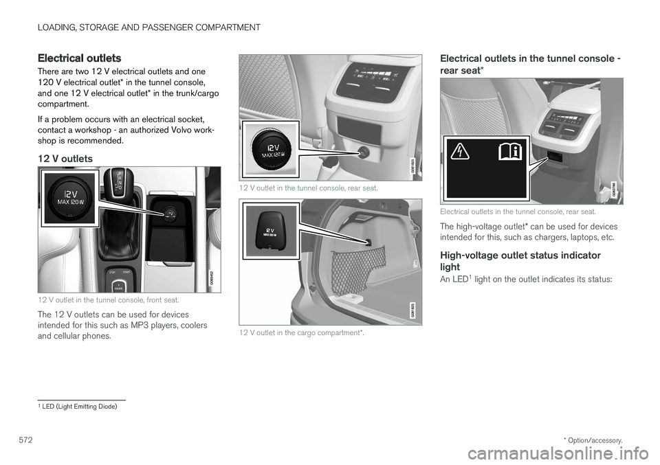
12 V outlets
12 V outlet in the tunnel console, front seat.
The 12 V outlets can be used for devices intended for this such as MP3 players, coolersand cellular phones.
12 V outlet in the tunnel console, rear seat.
12 V outlet in the cargo compartment *.
Electrical outlets in the tunnel console - rear seat *
Electrical outlets in the tunnel console, rear seat.
The high-voltage outlet * can be used for devices
intended for this, such as chargers, laptops, etc.
High-voltage outlet status indicator
light
An LED 1
light on the outlet indicates its status:
1 LED (Light Emitting Diode)
Page 575 of 674

LOADING, STORAGE AND PASSENGER COMPARTMENT
573
Status indicator lightCauseAction
Steady green light The socket is providing electrical current to a connected device. None.
Flashing orange light The socket's voltage converter is too hot (e.g. if the device draws too much cur- rent or if the temperature in the passenger compartment is very high). Unplug the device, let the voltage converter cool down and plug in the device again.
The connected device is drawing too much current (at the moment or con-stantly) or is not functioning properly. None. The device cannot be used in the socket.
Indicator light off The socket has not detected a device plugged into the socket. Make sure the device is correctly plugged into the socket.
The socket is not active. Make sure the vehicle's ignition is in at least mode I.
The socket has been active but has been deactivated. Start the engine and/or charge the start battery.
Related information
• Passenger compartment interior (p. 570)
• Using the electrical outlets (p. 574)
Page 576 of 674

LOADING, STORAGE AND PASSENGER COMPARTMENT
* Option/accessory.
574
Using the electrical outlets
The 12 V outlet can be used for devices intended for this such as MP3 players, coolersand cellular phones. The high-voltage outlet * can be used for devices
intended for this, such as chargers, laptops, etc.
The ignition must be in at least mode I for the
outlets to supply current. The outlets will then be active as long as there is sufficient charge in thestart battery. If the engine is turned off and the vehicle is locked, the outlets will be deactivated. If theengine is turned off and the vehicle remainsunlocked, the sockets will remain active for up to7 minutes.
NOTE
Bear in mind that using the electrical outlets when the engine is off could cause the starterbattery to have too low of a charge level,which could limit other functionality. Accessories connected to the electrical out- lets can be activated even when the vehicleelectrical system is off or if preconditioning isused. For this reason, disconnect plugs whenthey are not in use to prevent the starter bat-tery from becoming discharged.
WARNING
• Do not use accessories with large or heavy plugs – they could damage the out-let or come loose while you are driving.
• Do not use accessories that could causedisruptions to e.g. the vehicle's radioreceiver or electrical system.
• Position the accessory so that there is norisk of it injuring the driver or passengersin the event of heavy braking or a colli-sion.
• Pay attention to connected accessoriesas they can generate heat that could burnpassengers or the interior.
Using 12 V outlets1. Remove the stopper (tunnel console) or fold
down the cover (trunk/cargo compartment)over the socket and plug in the device.
2. Unplug the device and put the stopper back in (tunnel console) or fold up the cover(trunk/cargo compartment) when the socketis not in use or left unattended.
CAUTION
The maximum power is 120 W (10 A) per outlet.
Using high-voltage outletsThe ignition must be in at least mode I for outlets
to supply current. The outlets will then be active as long as there is sufficient charge in the startbattery. 1. Slide down the cover over the outlet and plug in the device. >
The LED 2
light on the outlet will indicate
its status.
2. The outlet is supplying electrical current when the light is glowing steadily green.
3. Disconnect the device by pulling out the plug (do not pull on the cord). Pull up the cover when the outlet is not in use or is left unattended.
CAUTION
The maximum power is 150 W.
WARNING
Do not attempt to alter or repair the high-volt- age outlet on your own. Volvo recommendscontacting an authorized Volvo workshop.
2LED (Light Emitting Diode)
Page 578 of 674

||
LOADING, STORAGE AND PASSENGER COMPARTMENT
* Option/accessory.
576
The illustration is generic – the design may vary.
To lock the glove compartment:
Insert the key into the lock on the glove com- partment.
Turn the key 90 degrees clockwise.
Remove the key from the lock.
–To unlock, perform the above steps in reverse.
Using the glove box as a cooled area *
The glove compartment can be used to cool e.g. drinks or food. Cooling is possible when the cli-mate system is active (i.e. when the ignition is in mode II or when the engine is running).
The illustration is generic – the design may vary.
Activate cooling
Deactivate cooling
–Activate or deactivate cooling by moving the control as far as possible toward the passen-ger compartment/glove compartment.
Related information
• Passenger compartment interior (p. 570)
• Private Locking (p. 256)
Sun visors In the ceiling in front of the driver and front pas- senger, there are sun visors that can be loweredand angled to the side as necessary.
The illustration is generic – the design may vary.
The mirror lighting
* comes on automatically when
the cover is lifted up. The mirror frame has a holder for e.g. cards or tickets.
Related information
• Passenger compartment interior (p. 570)
Page 583 of 674

LOADING, STORAGE AND PASSENGER COMPARTMENT
* Option/accessory.581
Fitting the tailgate flap
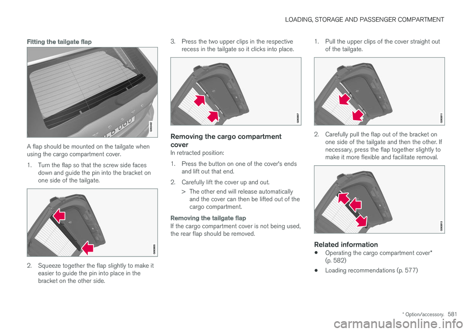
A flap should be mounted on the tailgate when using the cargo compartment cover.
1. Turn the flap so that the screw side faces
down and guide the pin into the bracket on one side of the tailgate.
2. Squeeze together the flap slightly to make iteasier to guide the pin into place in the bracket on the other side. 3. Press the two upper clips in the respective
recess in the tailgate so it clicks into place.
Removing the cargo compartment cover
In retracted position:
1. Press the button on one of the cover's endsand lift out that end.
2. Carefully lift the cover up and out. > The other end will release automaticallyand the cover can then be lifted out of the cargo compartment.
Removing the tailgate flap
If the cargo compartment cover is not being used, the rear flap should be removed. 1. Pull the upper clips of the cover straight out
of the tailgate.
2. Carefully pull the flap out of the bracket onone side of the tailgate and then the other. If necessary, press the flap together slightly tomake it more flexible and facilitate removal.
Related information
• Operating the cargo compartment cover
*
(p. 582)
• Loading recommendations (p. 577)
Page 584 of 674

LOADING, STORAGE AND PASSENGER COMPARTMENT
* Option/accessory.
582
Operating the cargo compartment
cover *
The cover can be used in two positions: fully open to completely cover the cargo compart-ment or partially retracted to make it easier toreach further into the cargo compartment.
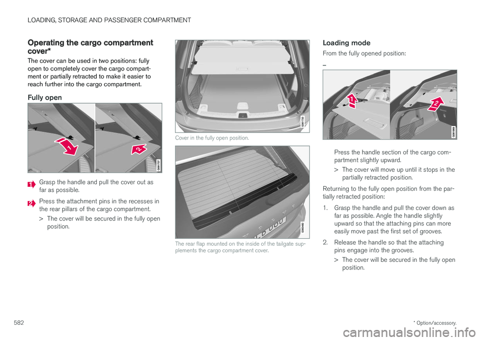
Fully open
Grasp the handle and pull the cover out as far as possible.
Press the attachment pins in the recesses in the rear pillars of the cargo compartment.
> The cover will be secured in the fully open position.
Cover in the fully open position.
The rear flap mounted on the inside of the tailgate sup- plements the cargo compartment cover.
Loading mode
From the fully opened position:
–
Press the handle section of the cargo com- partment slightly upward.
> The cover will move up until it stops in the partially retracted position.
Returning to the fully open position from the par- tially retracted position:
1. Grasp the handle and pull the cover down as far as possible. Angle the handle slightly upward so that the attaching pins can moreeasily move past the first set of grooves.
2. Release the handle so that the attaching pins engage into the grooves.
> The cover will be secured in the fully openposition.