2018 VOLVO XC60 T8 lock
[x] Cancel search: lockPage 577 of 674

LOADING, STORAGE AND PASSENGER COMPARTMENT
}}
* Option/accessory.575
WARNING
•Only use accessories that are not dam- aged or malfunctioning. The accessoriesmust be designed for 120 V and 60 Hz,with plugs intended for the outlet. Theaccessories must be CE marked, ULmarked or have an equivalent safetymarking.
• New let outlets, plugs or accessoriescome into contact with water or anotherfluid. Do not touch or use the outlet if itappears damaged or has been in contactwith water or another fluid.
• Do not connect power strips, adapters orextension cords to the outlet has thiscould cause the outlet's safety functionsto malfunction.
• The outlet is equipped with a pet guard.Make sure that no one picks at or dam-ages the outlet in such a way that theguard is disabled. Children should not beleft unsupervised in the vehicle when theoutlet is active.
Failure to follow the above could lead to severe or fatal electrical shocks.
Related information
• Electrical outlets (p. 572)
• Passenger compartment interior (p. 570)
Using the glove compartment
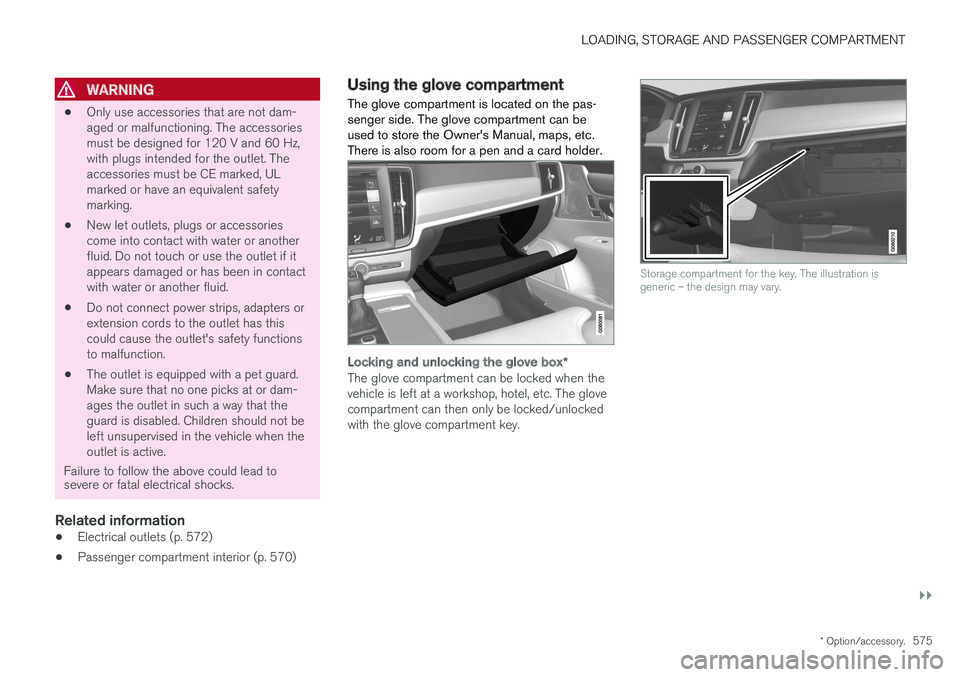
The glove compartment is located on the pas- senger side. The glove compartment can beused to store the Owner's Manual, maps, etc.There is also room for a pen and a card holder.
Locking and unlocking the glove box *
The glove compartment can be locked when the vehicle is left at a workshop, hotel, etc. The glovecompartment can then only be locked/unlockedwith the glove compartment key.
Storage compartment for the key. The illustration is generic – the design may vary.
Page 578 of 674

||
LOADING, STORAGE AND PASSENGER COMPARTMENT
* Option/accessory.
576
The illustration is generic – the design may vary.
To lock the glove compartment:
Insert the key into the lock on the glove com- partment.
Turn the key 90 degrees clockwise.
Remove the key from the lock.
–To unlock, perform the above steps in reverse.
Using the glove box as a cooled area *
The glove compartment can be used to cool e.g. drinks or food. Cooling is possible when the cli-mate system is active (i.e. when the ignition is in mode II or when the engine is running).
The illustration is generic – the design may vary.
Activate cooling
Deactivate cooling
–Activate or deactivate cooling by moving the control as far as possible toward the passen-ger compartment/glove compartment.
Related information
• Passenger compartment interior (p. 570)
• Private Locking (p. 256)
Sun visors In the ceiling in front of the driver and front pas- senger, there are sun visors that can be loweredand angled to the side as necessary.
The illustration is generic – the design may vary.
The mirror lighting
* comes on automatically when
the cover is lifted up. The mirror frame has a holder for e.g. cards or tickets.
Related information
• Passenger compartment interior (p. 570)
Page 582 of 674

LOADING, STORAGE AND PASSENGER COMPARTMENT
* Option/accessory.
580
Rear seat ski hatch
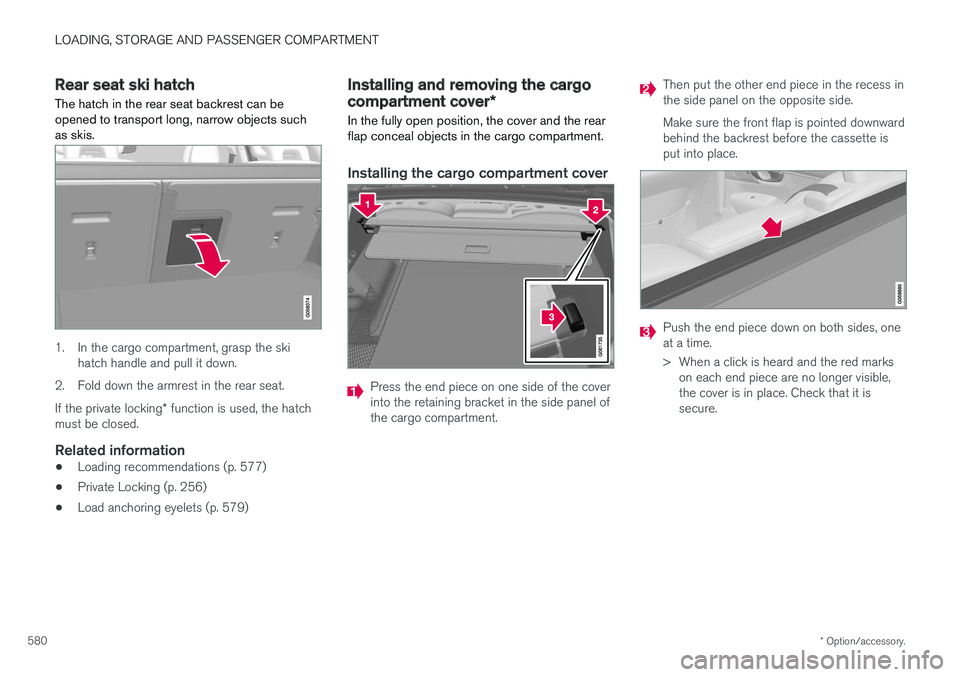
The hatch in the rear seat backrest can be opened to transport long, narrow objects suchas skis.
1. In the cargo compartment, grasp the ski hatch handle and pull it down.
2. Fold down the armrest in the rear seat. If the private locking * function is used, the hatch
must be closed.
Related information
• Loading recommendations (p. 577)
• Private Locking (p. 256)
• Load anchoring eyelets (p. 579)
Installing and removing the cargo
compartment cover
*
In the fully open position, the cover and the rear flap conceal objects in the cargo compartment.
Installing the cargo compartment cover
Press the end piece on one side of the cover into the retaining bracket in the side panel ofthe cargo compartment.
Then put the other end piece in the recess in the side panel on the opposite side. Make sure the front flap is pointed downward behind the backrest before the cassette isput into place.
Push the end piece down on both sides, one at a time.
> When a click is heard and the red marks on each end piece are no longer visible, the cover is in place. Check that it issecure.
Page 586 of 674

||
LOADING, STORAGE AND PASSENGER COMPARTMENT
* Option/accessory.
584
4. Screw the provided screw into place using
the provided 6 mm Allen wrench. Repeat on the other side. Recommended torque:20 Nm (15 ft-lb).
> Check to make sure the steel grid issecurely in place.
5. Return the backrest to the upright position. For more information on necessary tools and pro- cedures for installing/removing, see the assem-bly instructions provided with the steel grid.
CAUTION
The steel cargo grid cannot be folded up or down when a cargo compartment cover ismounted.
Related information
• Loading recommendations (p. 577)
• Load anchoring eyelets (p. 579)
Installing and removing the cargo
net
*
The cargo net helps prevent objects in the cargo compartment from entering the passenger com-partment in the event of a sudden stop or hardbraking.
The cargo net is attached at four points.
For safety reasons, the cargo net must always be mounted and secured according to the followingdescription. The net is made of strong nylon weave and can be attached in two different locations in the vehi-cle:
• Rear mounting - behind the rear seats.
• Front mounting - behind the front seats.
WARNING
Objects in the cargo compartment must always be securely anchored, even with a cor-rectly installed cargo net.
Installing the cargo net
WARNING
All of the cargo net's upper consoles, hooks and straps must be securely mounted andattached before the net is used. Never use the net if it is damaged.
NOTE
With front mounting, the cargo net is most easily installed via a rear door.
1. Fold out the cargo net and make sure that
the upper rod folds out and locks into posi- tion.
2. Insert one of the net's hooks into the front or rear ceiling mounting point with the straplock facing you.
Page 588 of 674

||
LOADING, STORAGE AND PASSENGER COMPARTMENT
586
Removing the cargo netThe cargo net can be easily removed and folded up.
1. Loosen the cargo net by pressing the buttonon the strap locks on each side and pulling to allow some slack.
2. Press in the catches and release both of the strap hooks.
3. Unhook the upper hooks and remove the net from the ceiling mounting points.
4. Press the red button on the rod so that it can be folded. Fold and roll up the net. Store thenet in its case.
Related information
• Loading recommendations (p. 577)
• Load anchoring eyelets (p. 579)
Page 592 of 674

||
MAINTENANCE AND SERVICE
590
Monthly:
•Check cold tire pressure in all tires. Inspect the tires for wear.
• Check that engine coolant and other fluidlevels are between the indicated "min" and"max" markings.
• Clean interior glass surfaces with a glasscleaner and soft paper towels.
• Wipe driver information displays with a softcloth.
• Visually inspect battery terminals for corro-sion. Corrosion may indicate a loose terminalconnector, or a battery near the end of itsuseful service life. Consult your Volvo retailerfor additional information.
As needed:
Wash the car, including the undercarriage, to reduce wear that can be caused by a buildup ofdirt, and corrosion that can be caused by salt res-idues. Clean leaves and twigs from air intake vents at the base of the windshield, and from other placeswhere they may collect.
NOTE
Complete service information for qualified technicians is available online for purchase orsubscription at www.volvotechinfo.com.
Related information
•Vehicle status (p. 592)
• Scheduling service and repairs (p. 593)
• Connecting equipment to the vehicle's data link connector (p. 36)
• Technician certification (p. 37)
• Climate control system service (p. 598)
• Maintenance of the brake system (p. 422)
• Engine compartment overview (p. 599)
Data transfer between vehicle andworkshop over Wi-Fi
Volvo workshops have a designated Wi-Fi net- work for secure data transfer between your vehi-cle and the workshop. Your visit to the workshopwill be easier and more effective when diagnos-tics information and software can be transferredover the workshop's network.
When you arrive at the workshop, your technician can connect your vehicle to the workshop's Wi-Finetwork to perform troubleshooting and down-load software. For this type of communication,the vehicle only connects to the workshop's net-work. The vehicle can only be connected to thedesignated workshop networks, not to any othernetwork, e.g. your home network.
Manual connection to workshop Wi-FiManual connection is usually performed by aservice technician. Because the technician usesthe buttons on your remote key to connect thevehicle, it is important that you bring a key withbuttons when taking the vehicle in to a workshop.Pressing the lock button on the remote key threetimes will connect the vehicle to the workshop'sWi-Fi network. When the car is connected to a Wi-Fi network, the
symbol appears in the center display.
Page 599 of 674

MAINTENANCE AND SERVICE
}}
597
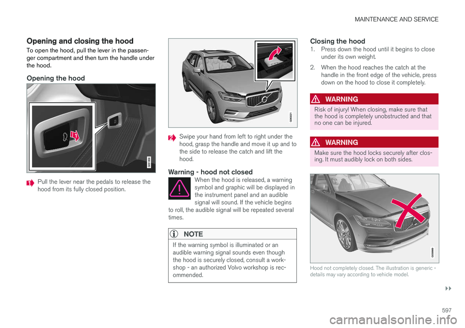
Opening and closing the hood To open the hood, pull the lever in the passen- ger compartment and then turn the handle underthe hood.
Opening the hood
Pull the lever near the pedals to release the hood from its fully closed position.
Swipe your hand from left to right under the hood, grasp the handle and move it up and tothe side to release the catch and lift thehood.
Warning - hood not closedWhen the hood is released, a warningsymbol and graphic will be displayed inthe instrument panel and an audiblesignal will sound. If the vehicle begins
to roll, the audible signal will be repeated severaltimes.
NOTE
If the warning symbol is illuminated or an audible warning signal sounds even thoughthe hood is securely closed, consult a work-shop - an authorized Volvo workshop is rec-ommended.
Closing the hood1. Press down the hood until it begins to close under its own weight.
2. When the hood reaches the catch at the handle in the front edge of the vehicle, press down on the hood to close it completely.
WARNING
Risk of injury! When closing, make sure that the hood is completely unobstructed and thatno one can be injured.
WARNING
Make sure the hood locks securely after clos- ing. It must audibly lock on both sides.
Hood not completely closed. The illustration is generic - details may vary according to vehicle model.
Page 623 of 674

MAINTENANCE AND SERVICE
}}
* Option/accessory.621
Positions
•Fuses 13-17 and 21-36 are "Micro" fuses.
• Fuses 1-12, 18-20 and 37 are "MCase" fuses and should only be replaced by a work- shop 19
.
FunctionAA
Heated rear window 30
– –
Pneumatic suspension * compressor 40
Lock motor for rear seat backrest, right side 15
– –
Lock motor for rear seat backrest, left side15
– –
Control module for reduction of nitrous oxides (diesel)30
Power tailgate
* 25
Power front passenger seat
*20
Towbar
* control module 40
FunctionAA
Seat belt tensioner module (right side) 40
Internal relay windings 5
Control module for reduction of nitrous oxides (diesel)15
Foot movement detection module for opening the power tailgate
*5
USB hub/accessory port –
– –
Towbar
* control module 25
Power driver seat
* 20
Seat belt tensioner module (left side) 40
Park Assist Camera
*5
– –
– –
– –
Feed when ignition is on 10
FunctionAA
Control module for airbags and seat belt tensioners 5
– –
Heated rear seat (left side)
*15
– –
Blind Spot Information (BLIS)
*;
Exterior reverse signal control mod- ule 5
– –
Modules for seat belt tensioners 5
Emissions system actuator (gaso- line, certain engine variants)
5
– –
– –
Heated rear seat (right side)
*15
– –
A
Ampere
19 An authorized Volvo workshop is recommended.