2018 VOLVO V90 CROSS COUNTRY tow
[x] Cancel search: towPage 351 of 662

DRIVER SUPPORT
* Option/accessory.349
Examples of further limitations
•Dirt, ice and snow covering the sensors may reduce functionality and prevent the systemfrom providing warnings. For additional infor-mation, see the section "Recommendedmaintenance for Cross Traffic Alert".
• CTA is automatically deactivated if a trailer,bicycle holder or similar is connected to thevehicle's electrical system.
• For CTA to function optimally, bicycle hold-ers, luggage racks or similar should not bemounted on the vehicle's towbar.
Related information
•
Cross Traffic Alert
* (p. 347)
Recommended maintenance forCross Traffic Alert
• For optimal performance, it is important to keep the areas in front of the sensors clean.
• Do not attach any objects, tape or decals tothe surface of the sensors.
Keep this area clean (on both the left and right sides of the vehicle) 91
.
The CTA sensors are located on the inside of each of the rear fenders/bumpers and are also used by the BLIS 92
and Rear Collision Warning
functions.
CAUTION
Repair of BLIS and CTA components or repainting of the bumper may only be per-formed by a workshop – an authorized Volvoworkshop is recommended.
Related information
• Cross Traffic Alert
* (p. 347)
• BLIS
* (p. 342)
• Rear Collision Warning (p. 341)
91
Note: This illustration is general and details may vary depending on model.
92 Blind Spot Information
Page 382 of 662

DRIVER SUPPORT
* Option/accessory.
380
Park Assist Camera *
The Park Assist Camera can help provide the driver when maneuvering in tight spaces by alert-ing the driver to obstacles using the camerascreen and graphics in the center display.
The Park Assist Camera is a support function that is automatically activated when reverse gearis engaged. It can also be started manually fromthe center display.
Example camera view 115
.
Zoom116
- zoom in/out
360° view* - activate/deactivate all cameras
PAS* - activate/deactivate Parking Assist
Lines - activate/deactivate trajectory lines
Towbar* - activate/deactivate trajectory lines
for towbar *117
CTA*
- activate/deactivate Cross Traffic Alert
WARNING
• The Parking Camera function is supple- mentary driver support intended to facili-tate driving and help make it safer – itcannot handle all situations in all traffic,weather and road conditions.
• The parking cameras have dead/blindspots where objects cannot be detected.
• Pay particular attention to people andanimals near the vehicle.
• Objects/obstacles may be closer to thevehicle than they appear on the screen.
• The parking cameras are not a substitutefor the driver's attention and judgment.The driver is always responsible forensuring the vehicle is driven in a safemanner, at the appropriate speed, with anappropriate distance to other vehicles,and in accordance with current trafficrules and regulations.
Related information
•Park Assist Camera views (p. 381)
• Park Assist Camera trajectory lines (p. 382)
• Sensor field from Park Assist for Park AssistCamera (p. 384)
• Starting the Park Assist Camera (p. 385)
• Park Assist Camera limitations (p. 385)
• Recommended maintenance of the ParkAssist Camera (p. 387)
• Recommended maintenance of the ParkAssist Camera (p. 387)
• Park Assist Camera symbols and messages(p. 388)
115
The illustration is generic - details may vary according to vehicle model.
116 The trajectory lines will not be displayed when zooming in.
117 Not available in all markets.
Page 383 of 662

DRIVER SUPPORT
}}
* Option/accessory.381
Park Assist Camera views
PAC can display a 360° panoramic view as well as separate views for each of the other cameras:rear, front, left and right.
360° view *
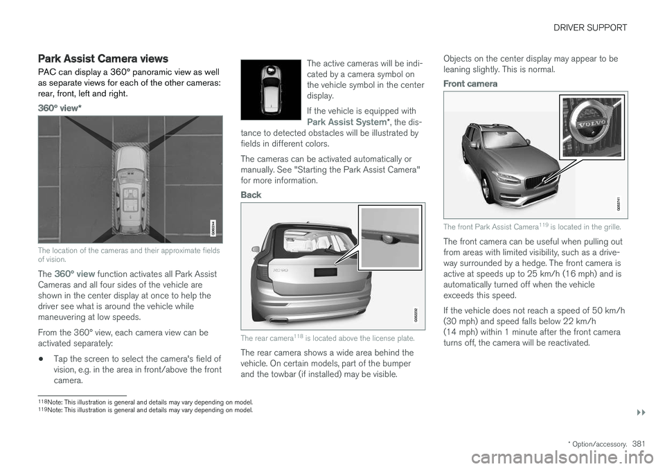
The location of the cameras and their approximate fields of vision.
The 360° view function activates all Park Assist
Cameras and all four sides of the vehicle are shown in the center display at once to help thedriver see what is around the vehicle whilemaneuvering at low speeds. From the 360° view, each camera view can be activated separately:
• Tap the screen to select the camera's field ofvision, e.g. in the area in front/above the frontcamera. The active cameras will be indi-cated by a camera symbol onthe vehicle symbol in the centerdisplay. If the vehicle is equipped with
Park Assist System*
, the dis-
tance to detected obstacles will be illustrated by fields in different colors.
The cameras can be activated automatically or manually. See "Starting the Park Assist Camera"for more information.
Back
The rear camera 118
is located above the license plate.
The rear camera shows a wide area behind the vehicle. On certain models, part of the bumperand the towbar (if installed) may be visible. Objects on the center display may appear to beleaning slightly. This is normal.
Front camera
The front Park Assist Camera
119
is located in the grille.
The front camera can be useful when pulling out from areas with limited visibility, such as a drive-way surrounded by a hedge. The front camera isactive at speeds up to 25 km/h (16 mph) and isautomatically turned off when the vehicleexceeds this speed. If the vehicle does not reach a speed of 50 km/h (30 mph) and speed falls below 22 km/h(14 mph) within 1 minute after the front cameraturns off, the camera will be reactivated.
118Note: This illustration is general and details may vary depending on model.
119 Note: This illustration is general and details may vary depending on model.
Page 384 of 662

||
DRIVER SUPPORT
* Option/accessory.
382
Side cameras
The side cameras 119
are located in the rearview mirrors.
The side cameras can show views along each side of the vehicle.
Related information
• Park Assist Camera
* (p. 380)
Park Assist Camera trajectory lines
The Park Assist Camera uses trajectory lines and fields on the screen to indicate the vehicle'sposition in relation to its immediate surround-ings.
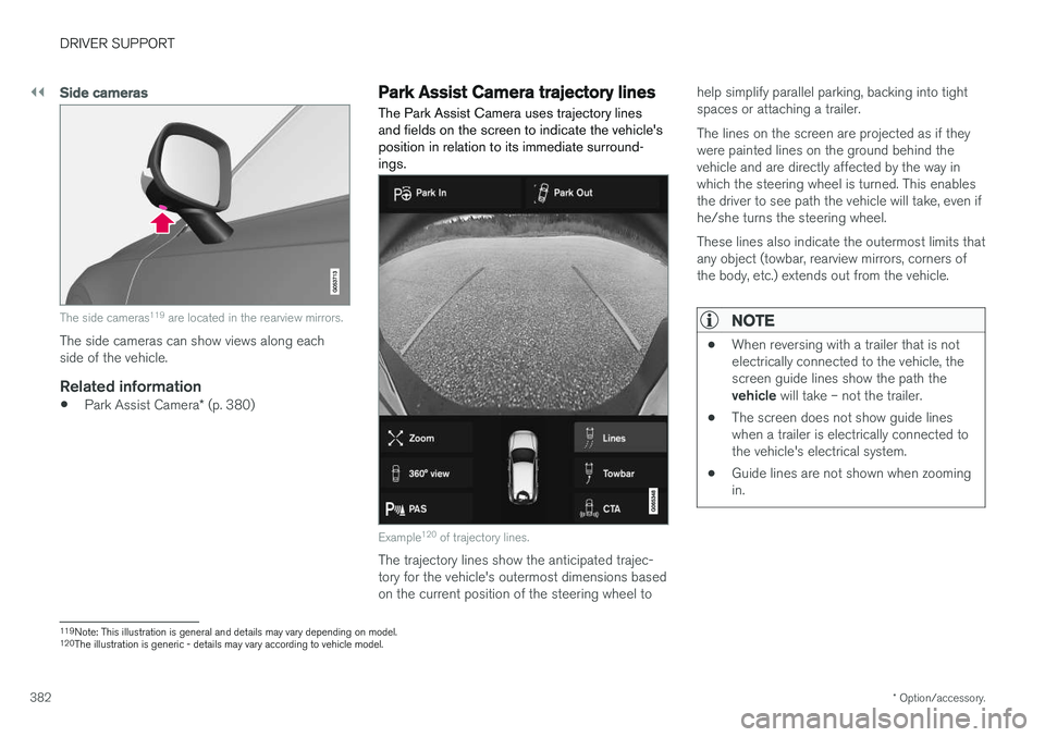
Example 120
of trajectory lines.
The trajectory lines show the anticipated trajec- tory for the vehicle's outermost dimensions basedon the current position of the steering wheel to help simplify parallel parking, backing into tightspaces or attaching a trailer. The lines on the screen are projected as if they were painted lines on the ground behind thevehicle and are directly affected by the way inwhich the steering wheel is turned. This enablesthe driver to see path the vehicle will take, even ifhe/she turns the steering wheel. These lines also indicate the outermost limits that any object (towbar, rearview mirrors, corners ofthe body, etc.) extends out from the vehicle.
NOTE
•
When reversing with a trailer that is not electrically connected to the vehicle, thescreen guide lines show the path the vehicle
will take – not the trailer.
• The screen does not show guide lines when a trailer is electrically connected tothe vehicle's electrical system.
• Guide lines are not shown when zoomingin.
119
Note: This illustration is general and details may vary depending on model.
120 The illustration is generic - details may vary according to vehicle model.
Page 385 of 662

DRIVER SUPPORT
}}
* Option/accessory.383
CAUTION
•Bear in mind that when the rearward camera view is selected, the screen onlyshows the area behind the vehicle – payattention to the sides and front of thevehicle when steering while reversing.
• The same applies to the reverse – payattention to what is happening with therear parts of the vehicle when the frontcamera view is selected.
• Note that the guide lines show the
short-
est path – pay extra attention to ensure
that the vehicle sides do not come incontact with/travel over anything whensteering while driving forward or that thevehicle front moves toward/over anythingwhen steering while reversing.
Trajectory lines in 360° view *
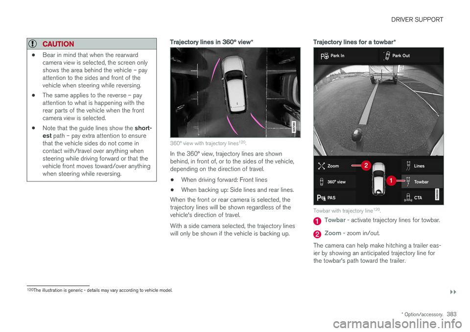
360° view with trajectory lines120
.
In the 360° view, trajectory lines are shown behind, in front of, or to the sides of the vehicle,depending on the direction of travel.
• When driving forward: Front lines
• When backing up: Side lines and rear lines.
When the front or rear camera is selected, thetrajectory lines will be shown regardless of thevehicle's direction of travel. With a side camera selected, the trajectory lines will only be shown if the vehicle is backing up.
Trajectory lines for a towbar *
Towbar with trajectory line120
.
Towbar - activate trajectory lines for towbar.
Zoom - zoom in/out.
The camera can help make hitching a trailer eas- ier by showing an anticipated trajectory line for the towbar's path toward the trailer.
120 The illustration is generic - details may vary according to vehicle model.
Page 386 of 662

||
DRIVER SUPPORT
* Option/accessory.
384 1.
Tap
Towbar (1).
> The trajectory line for the towbar's antici- pated path toward the vehicle will appear and the vehicle's trajectory lines will dis-appear. Trajectory lines cannot be displayed for both the vehicle and the towbar at thesame time.
2. Tap
Zoom (2) for a close-up view for more
precise maneuvering.
> The camera will zoom in.
Related information
• Park Assist Camera
* (p. 380)
Sensor field from Park Assist forPark Assist Camera
If the vehicle is equipped with Park Assist, dis- tances will be shown in the 360° view with col-ored fields for each sensor that has detected anobstacle.
Front and rear sensors
The screen can display colored sensor fields on the vehicle symbol 121
.
The front and rear fields change colors (from yel- low to orange to red) as the vehicle moves closerto an obstacle.
Front and rear fieldcolorsDistance in meters(feet)
Yellow 0.6-1.5 (2.0-4.9)
Orange 0.4-0.6 (1.3-2.0)
Red 0-0.4 (0-1.3)
Side sensor fields
The side sensor fields will only be shown in orange.
Side field colorDistance in meters (feet)
Orange 0-0.3 (0-1.0)
Related information
• Park Assist Camera
* (p. 380)
121
The illustration is generic - details may vary according to vehicle model.
Page 396 of 662

DRIVER SUPPORT
* Option/accessory.
394
Park Assist Pilot * limitations
Park Assist Pilot PAP 126
may not be able to
detect all conditions in all situations and func- tionality may therefore be limited.WARNING
• The PAP function is supplementary driver support intended to facilitate driving andhelp make it safer – it cannot handle allsituations in all traffic, weather and roadconditions.
• Pay particular attention to people andanimals near the vehicle.
• Bear in mind that the front end of thevehicle may swing out towards oncomingtraffic during the parking maneuver.
• Objects situated higher than the detec-tion area of the sensors are not includedwhen the parking maneuver is calculated,which could cause PAP to swing into theparking space too early. Such parkingspaces should be avoided for this reason.
• PAP is not a substitute for the driver'sattention and judgment. The driver isalways responsible for ensuring the vehi-cle is driven in a safe manner, at theappropriate speed, with an appropriatedistance to other vehicles, and in accord-ance with current traffic rules and regula-tions.
The driver should be aware of the following limi-tations for Park Assist Pilot:
The parking sequence is cancelledA parking sequence will be cancelled if:
• the driver moves the steering wheel
• the vehicle's speed exceeds 7 km/h (4 mph)
• the driver taps
Cancel in the center display
• when the anti-lock brakes or the Electronic stability control are engaged - e.g. when awheel loses grip on a slippery road
• when the power steering works at reduced power - e.g. during cooling due to overheat- ing (see section "Speed-dependent steeringforce").
A message in the center display will explain whythe parking sequence was cancelled.
CAUTION
Under certain circumstances, PAP may not be able to find parking spaces – one reason maybe that the sensors are disrupted by externalsound sources that emit the same ultrasonicfrequencies that the system works with. Examples of such sources include horns, wet tires on asphalt, pneumatic brakes, exhaustnoise from motorcycles, etc.
126 Park Assist Pilot
Page 403 of 662

STARTING AND DRIVING
}}
401
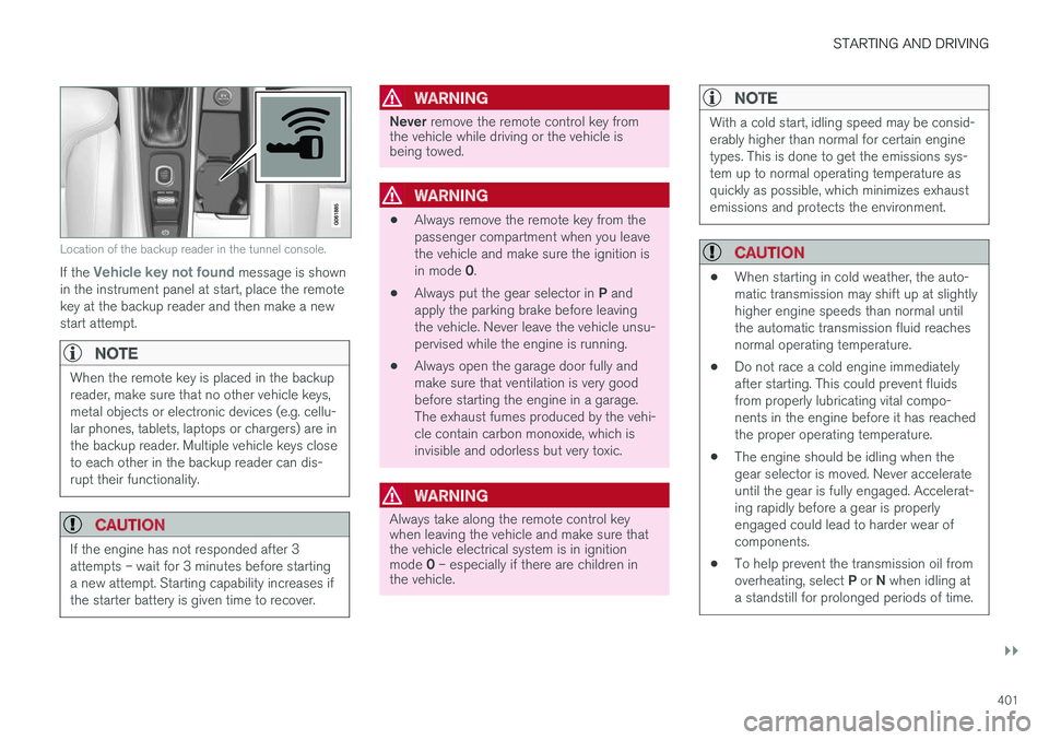
Location of the backup reader in the tunnel console.
If the Vehicle key not found message is shown
in the instrument panel at start, place the remote key at the backup reader and then make a newstart attempt.
NOTE
When the remote key is placed in the backup reader, make sure that no other vehicle keys,metal objects or electronic devices (e.g. cellu-lar phones, tablets, laptops or chargers) are inthe backup reader. Multiple vehicle keys closeto each other in the backup reader can dis-rupt their functionality.
CAUTION
If the engine has not responded after 3 attempts – wait for 3 minutes before startinga new attempt. Starting capability increases ifthe starter battery is given time to recover.
WARNING
Never remove the remote control key from
the vehicle while driving or the vehicle is being towed.
WARNING
• Always remove the remote key from the passenger compartment when you leavethe vehicle and make sure the ignition is in mode
0.
• Always put the gear selector in
P and
apply the parking brake before leaving the vehicle. Never leave the vehicle unsu-pervised while the engine is running.
• Always open the garage door fully andmake sure that ventilation is very goodbefore starting the engine in a garage.The exhaust fumes produced by the vehi-cle contain carbon monoxide, which isinvisible and odorless but very toxic.
WARNING
Always take along the remote control key when leaving the vehicle and make sure thatthe vehicle electrical system is in ignition mode
0 – especially if there are children in
the vehicle.
NOTE
With a cold start, idling speed may be consid- erably higher than normal for certain enginetypes. This is done to get the emissions sys-tem up to normal operating temperature asquickly as possible, which minimizes exhaustemissions and protects the environment.
CAUTION
• When starting in cold weather, the auto- matic transmission may shift up at slightlyhigher engine speeds than normal untilthe automatic transmission fluid reachesnormal operating temperature.
• Do not race a cold engine immediatelyafter starting. This could prevent fluidsfrom properly lubricating vital compo-nents in the engine before it has reachedthe proper operating temperature.
• The engine should be idling when thegear selector is moved. Never accelerateuntil the gear is fully engaged. Accelerat-ing rapidly before a gear is properlyengaged could lead to harder wear ofcomponents.
• To help prevent the transmission oil from overheating, select
P or N when idling at
a standstill for prolonged periods of time.