2018 VOLVO V60 CROSS COUNTRY warning
[x] Cancel search: warningPage 150 of 404
LOADING AND STORAGE
148
Grocery bag holder
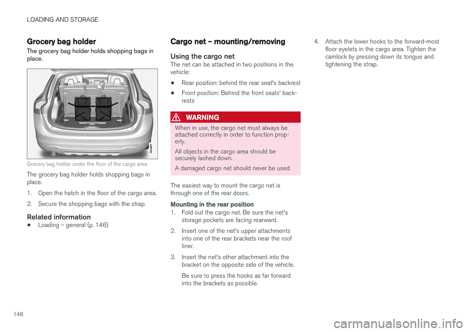
The grocery bag holder holds shopping bags in place.
Grocery bag holder under the floor of the cargo area
The grocery bag holder holds shopping bags in place.
1. Open the hatch in the floor of the cargo area.
2. Secure the shopping bags with the strap.
Related information
• Loading – general (p. 146)
Cargo net – mounting/removing
Using the cargo netThe net can be attached in two positions in the vehicle:
• Rear position: behind the rear seat's backrest
• Front position: Behind the front seats' back-rests
WARNING
When in use, the cargo net must always be attached correctly in order to function prop-erly. All objects in the cargo area should be securely lashed down. A damaged cargo net should never be used.
The easiest way to mount the cargo net is through one of the rear doors.
Mounting in the rear position
1. Fold out the cargo net. Be sure the net's storage pockets are facing rearward.
2. Insert one of the net's upper attachments into one of the rear brackets near the roof liner.
3. Insert the net's other attachment into the bracket on the opposite side of the vehicle. Be sure to press the hooks as far forward into the brackets as possible. 4. Attach the lower hooks to the forward-most
floor eyelets in the cargo area. Tighten thecamlock by pressing down its tongue andtightening the strap.
Page 154 of 404
LOCKS AND ALARM
152
Remote key and key blade
Two remote keys are provided with your vehicle. They enable you to unlock the doors and tail-gate, and also function as ignition keys to startthe vehicle or operate electrical components.The remote keys contain detachable metal keyblades for manually locking or unlocking the driv-er's door and the glove compartment. The visibleends of these key blades are unique to make iteasier to identify "your" remote key. Up to sixremotes can be programmed for use on thesame vehicle.
WARNING
Never leave the remote key in the ignition slot if children are to remain in the vehicle.
For more information on the various ignition modes, see Ignition modes (p. 82).
Related information
• Remote key – functions (p. 155)
• Remote key – functions (p. 155)
• Remote key – range (p. 156)
Remote key – loss
If either of the remote keys (p. 152) is lost, the other should be taken with the vehicle to a Volvoretailer. As an anti-theft measure, the code of thelost remote key must be erased from the system.
NOTE
Additional or duplicate remote control keys can be obtained from any authorized Volvoretailer. You can also obtain additional or duplicate remote control keys from certain independentrepair facilities and locksmiths that are quali-fied to make remote control keys. Each keymust be programmed to work with your vehi-cle. California Only: A list of independent repair facilities and/or locksmiths known to Volvo that can cut andcode replacement keys can be found: • on the Volvo website at http://www.volvocars.com/us/keys
• by calling Volvo Customer Care at1-800-458-1552
The number of registered keys for the vehicle can be found by pressing
MY CAR and going into
SettingsInformationNumber of keys.For a description of the menu system, see My Car – introduction (p. 79). USA-5WK49264FCC ID:KR55WK49264 + Siemens VDO 5WK49236 FCC ID:KR55WK49236, 5WK49266FCC ID:KR55WK49266 + Siemens VDO 5WK49233 FCC ID:KR55WK49233This device complies with part 15 of the FCC rules and RSS-210. Operation is subject to thefollowing conditions: (1) This device may notcause harmful interference, and (2) this devicemust accept any interference received, includinginterference that may cause undesired operation. Canada-5WK49264IC:267T-5WK49264 + Siemens VDO 5WK49236 IC:267T-5WK49236, 5WK49266IC:267T-5WK49266 + Siemens VDO 5WK49233 IC:267T-5WK49233Operation is subject to the following conditions: (1) this device may not cause interference, and(2) this device must accept any interference,including interference that may cause undesiredoperation of the device.
Page 167 of 404
LOCKS AND ALARM
* Option/accessory.165
WARNING
People with implanted pacemakers should not allow the pacemaker to come closer than9 inches (22 cm) to any of the keyless drivesystem's antennas. This is to help preventinterference between the pacemaker and thekeyless drive system.
Related information
•Keyless drive
*– locking/unlocking (p. 161)
Locking/unlocking – from the outside
The remote key (p. 152) is used to lock/unlock all of the doors and the tailgate at the same time.Different settings for unlocking the vehicle canbe selected, see Remote key – functions(p. 155). Before the vehicle can be locked from the out- side with the remote key, the driver's door mustbe closed. If the tailgate or any other door isopen, it will be locked and the alarm will bearmed.
NOTE
Be sure the remote key is outside of the vehi- cle before the other doors/tailgate are closedto help avoid locking the remote inside thevehicle.
If the vehicle is equipped with the optional key- less drive system, all doors/tailgate must beclosed before the vehicle can be locked. The first press on the unlock button unlocks the driver's door and a second press unlocks theother doors and the tailgate (see also remote keyand key blade (p. 152)). This setting can be changed in the menu system. See MY
CAR (p. 79) for a description.
If the locks repeatedly do not react when the unlock button is pressed, it may be necessary to replace the battery in the remote, see Remotekey – replacing the battery (p. 159). In this casethe vehicle can be unlocked with the detachablekey blade (p. 158).
Related information
•
Locking/unlocking – from inside (p. 166)
Page 172 of 404
LOCKS AND ALARM
170
Alarm – general information
The alarm system provides a warning if an attempt is made to break into the vehicle. The alarm is automatically armed (p. 171) whenever the vehicle is locked with the remotekey. When armed, the alarm continuously monitors a number of points on the vehicle. The followingconditions will trigger the alarm:
• The hood is forced open.
• The tailgate is forced open.
• A door is forced open.
• The ignition slot is tampered with.
• An attempt is made to start the vehicle with a non-approved key (a key not coded to thecar's ignition).
• The battery is disconnected (while the alarmis armed).
• The siren is disconnected when the alarm isdisarmed.
A message will appear in the information displayif a fault should occur in the alarm system. Con-tact a trained and qualified Volvo service techni-cian.
NOTE
Do not attempt to repair any of the compo- nents in the alarm system yourself. This couldaffect the insurance policy on the vehicle.
Related information
• Alarm – turning off (p. 172)
• Alarm signal (p. 171)
• Alarm indicator (p. 170)
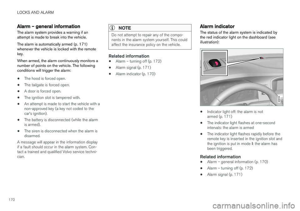
Alarm indicator
The status of the alarm system is indicated by the red indicator light on the dashboard (seeillustration):
• Indicator light off: the alarm is not armed (p. 171)
• The indicator light flashes at one-secondintervals: the alarm is armed
• The indicator light flashes rapidly before theremote key is inserted in the ignition slot and the ignition is put in mode
I: the alarm has
been triggered.
Related information
• Alarm – general information (p. 170)
• Alarm – turning off (p. 172)
• Alarm signal (p. 171)
Page 173 of 404
LOCKS AND ALARM
171
Alarm – arming/disarming The alarm system provides a warning if an attempt is made to break into the vehicle.
Arming the alarm
–Press the Lock button on the remote key. One long flash of the turn signals will confirmthat the alarm (p. 170) is armed.
Alarm confirmation settings can be changed in MY CAR , under
Car settingsLock settings
Keyless entry. For a description of the menu
system, see My Car – introduction (p. 79).
USA FCC ID: MAYDA 5823(3) This device complies with part 15 of the FCC rules. Operation is subject to the following condi-tions: (1) This device may not cause harmfulinterference, and (2) this device must accept anyinterference received, including interference thatmay cause undesired operation.
Canada IC: 4405A-DA 5823(3)
This device is subject to the following conditions:(1) this device may not cause interference, and(2) this device must accept any interference,including interference that may cause undesiredoperation of the device.
Disarming the alarm
–Press the Unlock button on the remote key.
> Two short flashes from the car's direction indicators confirm that the alarm has been deactivated and that all doors areunlocked.
Related information
• Alarm indicator (p. 170)
• Alarm signal (p. 171)
• Alarm – turning off (p. 172)
• Alarm-related functions (p. 172)
Alarm signal
An audible (p. 170) signal is given by a battery powered siren. The alarm cycle lasts for 30 sec-onds.
The visual alarm signal is given by flashing all turn signals for approximately 5 minutes or untilthe alarm is turned off.
Related information
• Alarm indicator (p. 170)
• Alarm – arming/disarming (p. 171)
• Alarm – turning off (p. 172)
Page 174 of 404
LOCKS AND ALARM
172
Alarm – turning off
The alarm system provides a warning if an attempt is made to break into the vehicle.
If the alarm is sounding, it can be stopped by pressing the Unlock button on the remote key orby inserting the remote key in the ignition slot.Two short flashes from the car's turn signals con-firm that the alarm has been turned off.
Related information
• Alarm indicator (p. 170)
• Alarm – arming/disarming (p. 171)
• Remote key – replacing the battery (p. 159)
Alarm-related functions
The following is general information regarding the alarm system in your vehicle.
Automatic re-armingIf the doors are unlocked, the locks will automati- cally re-engage (re-lock) and the alarm will re-arm after 2 minutes unless a door or the tailgatehas been opened.
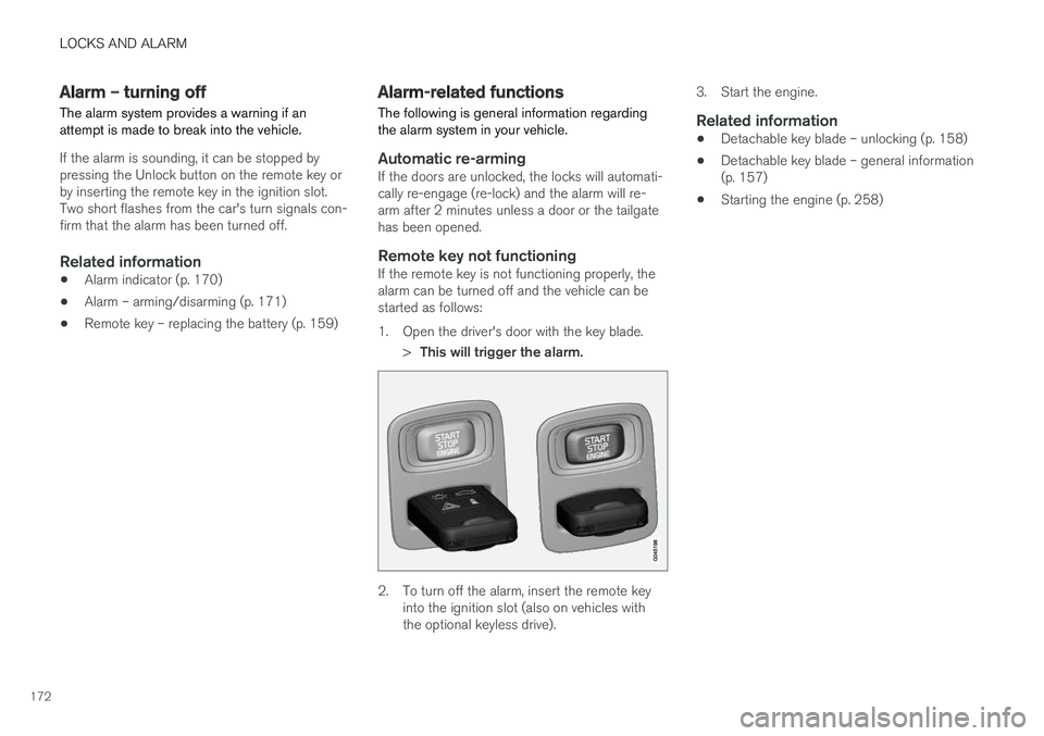
Remote key not functioningIf the remote key is not functioning properly, thealarm can be turned off and the vehicle can bestarted as follows:
1. Open the driver's door with the key blade.
>This will trigger the alarm.
2. To turn off the alarm, insert the remote key
into the ignition slot (also on vehicles with the optional keyless drive). 3. Start the engine.
Related information
•
Detachable key blade – unlocking (p. 158)
• Detachable key blade – general information(p. 157)
• Starting the engine (p. 258)
Page 176 of 404
DRIVER SUPPORT
174
Stability system – introduction The Electronic Stability Control (ESC) system consists of a number of functions designed tohelp reduce wheel spin, counteract skidding andto generally help improve directional stability.
A pulsating sound will be audible when the system is actively operating and isnormal. Acceleration will also beslightly slower than normal.
WARNING
•The stability system (ESC) is intended to help improve driving safety but cannotdeal with all situations, or traffic, road andweather conditions. Speed and drivingstyle should always be adapted to thecurrent driving situation.
• ESC supplements, but can never replace,the driver's judgment and responsibilitywhen operating the vehicle. The driver isalways responsible for operating the vehi-cle in a safe manner in accordance withapplicable traffic regulations.
ESC consists of the following functions:
• Traction control
• Spin control
• Active Yaw Control
• Engine Drag Control •
Corner Traction Control
Traction Control (TC)
This function is designed to help reduce wheel spin at low speeds by transferring power from adrive wheel that begins to lose traction to thewheel on the opposite side of the vehicle (on thesame axle).
Spin Control (SC)
The SC function is designed to help prevent the drive wheels from spinning while the vehicle isaccelerating.
Active Yaw Control (AYC)
This function helps maintain directional stability, for example when cornering, by braking one ormore of the wheels if the vehicle shows a ten-dency to skid or slide laterally.
Corner Traction Control (CTC)
CTC compensates for understeering and helps provide additional stability when acceleratingthrough a curve by preventing the inside wheelfrom spinning. This is particularly useful whenaccelerating on a curving highway on-ramp. CTC is most effective if the stability system's Sport
mode is selected. See the section about
Sport mode.
Engine Drag Control (EDC)
EDC helps keep the engine running if the wheels show a tendency to lock, e.g., when shifting downin the Geartronic manual shifting mode or whileusing the engine's braking function on a slipperysurface. If the engine were to stop, power steer- ing would not function, making the vehicle moredifficult to steer.
Trailer Stability Assist (TSA)
The TSA helps stabilize a vehicle that is towing a trailer when the vehicle and trailer have begun tosway. See Trailer Stability Assist (TSA) (p. 294)for more information. This system is automatically deactivated if the driver selects
Sport mode.
Related information
•Stability system – operation (p. 175)
• Stability system – symbols and messages (p. 176)
• Trailer Stability Assist (TSA) (p. 294)
Page 179 of 404
DRIVER SUPPORT
177
SymbolMessage Description
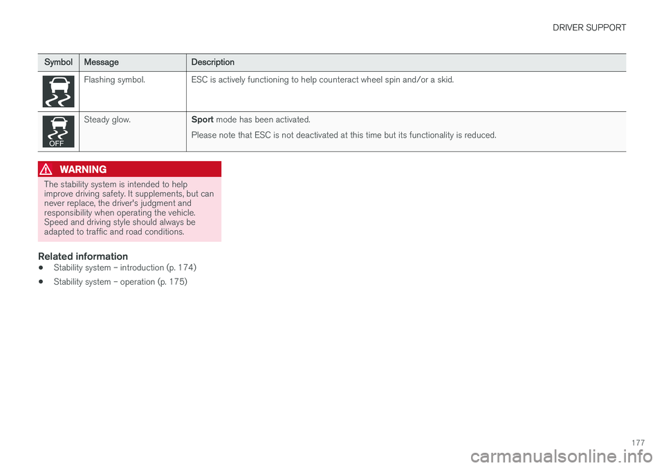
Flashing symbol. ESC is actively functioning to help counteract wheel spin and/or a skid.
Steady glow.
Sport mode has been activated.
Please note that ESC is not deactivated at this time but its functionality is reduced.
WARNING
The stability system is intended to help improve driving safety. It supplements, but cannever replace, the driver's judgment andresponsibility when operating the vehicle.Speed and driving style should always beadapted to traffic and road conditions.
Related information
• Stability system – introduction (p. 174)
• Stability system – operation (p. 175)