Page 351 of 404
MAINTENANCE AND SERVICING
349
Related information
•Bulbs – specifications (p. 351)
Bulbs – taillight housing The backup lights, fog lights and turn signals are replaced from inside the cargo area
Brake light (LED)
Parking lights/side marker light (LED)
Turn signal
Brake light (LED)
Backup light
Rear fog light
1. Open the panel.
2. Pull the insulation in front of the bulb holder
straight out.
3. Press down the catch and pull out the bulb holder.
4. Remove the defective bulb by pressing it in and turning it counterclockwise.
5. Press a new bulb into place and turn it clock- wise.
6. Hold down the catch and press the bulb holder back into place.
7. Put the insulation and panel back in place.
Related information
• Bulbs – introduction (p. 344)
• Bulbs – specifications (p. 351)
Page 353 of 404
MAINTENANCE AND SERVICING
}}
* Option/accessory.351
Bulbs – specifications The following bulbs can be replaced by the vehi- cles owner. All other bulbs should only bereplaced by a trained and qualified Volvo servicetechnician.
Lighting function Wat-
tage Bulb
Low beam (halo- gen) 55 H11 LL
High beam (halo-gen) 65 H9
Extra high beam(models withActive Bending Lights *) 55 H7 LL
Front turn signals 24 PY24W License plate light- ing 5 C5W LL
Vanity mirror light-ing 1.2 W2x4.6d type
T5
Glove compart-ment lighting 5 SV8.5 (length
43mm)
Rear turn signals 21 PY21W LL
Rear fog light 21 H21W LL
Lighting function Wat-
tage Bulb
Backup light 21 H21W LL
Brake light 21 P21W LL
Cargo area lighting 5 SV8.5 (length 43mm)
Front footwell lighting 3 W2, 1x9.5d
type T10
NOTE
Please consult a Volvo retailer
Page 367 of 404
MAINTENANCE AND SERVICING
* Option/accessory.365
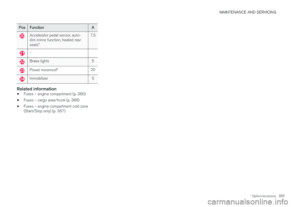
PosFunction A
Accelerator pedal sensor, auto- dim mirror function, heated rear seats* 7.5
-
Brake lights 5
Power moonroof
* 20
Immobilizer 5
Related information
•Fuses – engine compartment (p. 360)
• Fuses – cargo area/trunk (p. 366)
• Fuses – engine compartment cold zone (Start/Stop only) (p. 367)
Page 372 of 404
||
MAINTENANCE AND SERVICING
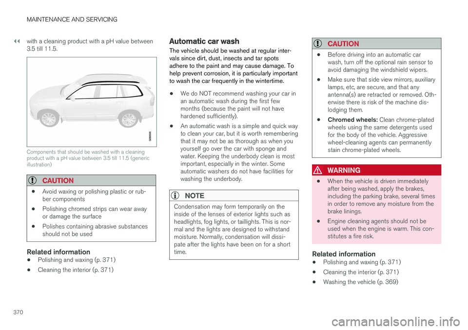
370with a cleaning product with a pH value between 3.5 till 11.5.
Components that should be washed with a cleaning product with a pH value between 3.5 till 11.5 (genericillustration)
CAUTION
•
Avoid waxing or polishing plastic or rub- ber components
• Polishing chromed strips can wear awayor damage the surface
• Polishes containing abrasive substancesshould not be used
Related information
• Polishing and waxing (p. 371)
• Cleaning the interior (p. 371)
Automatic car wash
The vehicle should be washed at regular inter- vals since dirt, dust, insects and tar spotsadhere to the paint and may cause damage. Tohelp prevent corrosion, it is particularly importantto wash the car frequently in the wintertime.
• We do NOT recommend washing your car in an automatic wash during the first fewmonths (because the paint will not havehardened sufficiently).
• An automatic wash is a simple and quick wayto clean your car, but it is worth rememberingthat it may not be as thorough as when youyourself go over the car with sponge andwater. Keeping the underbody clean is mostimportant, especially in the winter. Someautomatic washers do not have facilities forwashing the underbody.
NOTE
Condensation may form temporarily on the inside of the lenses of exterior lights such asheadlights, fog lights, or taillights. This is nor-mal and the lights are designed to withstandmoisture. Normally, condensation will dissi-pate after the lights have been on for a shorttime.
CAUTION
•
Before driving into an automatic car wash, turn off the optional rain sensor toavoid damaging the windshield wipers.
• Make sure that side view mirrors, auxiliarylamps, etc, are secure, and that anyantenna(s) are retracted or removed. Oth-erwise there is risk of the machine dis-lodging them.
• Chromed wheels:
Clean chrome-plated
wheels using the same detergents usedfor the body of the vehicle. Aggressivewheel-cleaning agents can permanentlystain chrome-plated wheels.
WARNING
• When the vehicle is driven immediately after being washed, apply the brakes,including the parking brake, several timesin order to remove any moisture from thebrake linings.
• Engine cleaning agents should not beused when the engine is warm. This con-stitutes a fire risk.
Related information
•
Polishing and waxing (p. 371)
• Cleaning the interior (p. 371)
• Washing the vehicle (p. 369)
Page 391 of 404

SPECIFICATIONS
389
with necessary information about one of the vehi- cle's systems.
Related information
•
Information displays – indicator symbols(p. 75)
• Information displays – warning symbols(p. 77)
• Information display – messages (p. 117)
Warning symbols
The following tables list the most common warn- ing and indicator lights and symbols and a refer-ence to where more detailed information can befound.
: The red warning symbol illuminates to
indicate a problem related to safety and/or driva- bility. A message will also appear in the maininstruments panel's display.
: The information symbol illuminates and a
text message is displayed to provide the driver with necessary information about one of thevehicle's systems.
Symbols in the main instrument panel
Warning symbols in the instrument panel
Symbol Description See
Low oil pressure (p. 77)
Parking brakeA
(p. 77)
SRS airbags (p. 77)
Seat belt reminder (p. 77)
Generator not charging (p. 77)
SymbolDescription See
Fault in the brake system (p. 77)
Warning symbol (p. 77)
A
The symbol is Park only on models with the optional digital
instrument panel.
Related information
• Information displays – indicator symbols (p. 75)
• Information displays – warning symbols(p. 77)
• Information display – messages (p. 117)
Page 392 of 404
SPECIFICATIONS
* Option/accessory.
390
Indicator symbols
The following tables list the most common warn- ing and indicator lights and symbols and a refer-ence to where more detailed information can befound.
: The red warning symbol illuminates to
indicate a problem related to safety and/or driva- bility. A message will also appear in the maininstruments panel's display.
: The information symbol illuminates and a
text message is displayed to provide the driver with necessary information about one of thevehicle's systems.
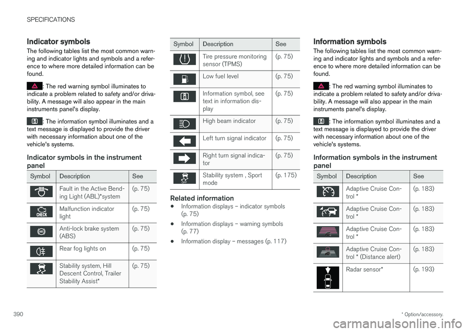
Indicator symbols in the instrument panel
Symbol Description See
Fault in the Active Bend- ing Light (ABL)*system (p. 75)
Malfunction indicator light
(p. 75)
Anti-lock brake system (ABS)(p. 75)
Rear fog lights on (p. 75)
Stability system, Hill Descent Control, Trailer Stability Assist
*(p. 75)
Symbol
Description See
Tire pressure monitoring sensor (TPMS)(p. 75)
Low fuel level (p. 75)
Information symbol, see text in information dis-play(p. 75)
High beam indicator (p. 75)
Left turn signal indicator (p. 75)
Right turn signal indica- tor
(p. 75)
Stability system , Sport mode(p. 175)
Related information
•
Information displays – indicator symbols (p. 75)
• Information displays – warning symbols(p. 77)
• Information display – messages (p. 117)
Information symbols
The following tables list the most common warn- ing and indicator lights and symbols and a refer-ence to where more detailed information can befound.
: The red warning symbol illuminates to
indicate a problem related to safety and/or driva- bility. A message will also appear in the maininstruments panel's display.
: The information symbol illuminates and a
text message is displayed to provide the driver with necessary information about one of thevehicle's systems.
Information symbols in the instrument panel
Symbol Description See
Adaptive Cruise Con- trol * (p. 183)
Adaptive Cruise Con- trol
* (p. 183)
Adaptive Cruise Con- trol
* (p. 183)
Adaptive Cruise Con- trol
* (Distance alert) (p. 183)
Radar sensor
*(p. 193)
Page 393 of 404

SPECIFICATIONS
* Option/accessory.391
SymbolDescription See
Camera sensor, laser sensor(p. 215)(p. 208)
Collision Warning with Full Auto-brake and Pedestrian Detection
*(p. 220)
Active Bending Lights (ABL)
* (p. 95)
Driver Alert System
*(p. 222)
Driver Alert System
*(p. 222)
Parking brake (p. 280)
Rain sensor
* (p. 103)
Active High Beams (AHB)
* (p. 94)
Windshield sensor
*(p. 94)
Symbol
Description See
Driver Alert System*
(Lane Departure Warning/LaneKeeping Aid) (p. 228)
Driver Alert System
*
(Lane Departure Warning/LaneKeeping Aid) (p. 228)
Driver Alert System
*
(Lane Departure Warning/LaneKeeping Aid) (p. 228)
Fuel tank on passeng- er's side of the vehicle
(p. 289)
Related information
•
Information displays – indicator symbols (p. 75)
• Information displays – warning symbols(p. 77)
• Information display – messages (p. 117)
Information symbols – ceiling console
The following tables list the most common warn- ing and indicator lights and symbols and a refer-ence to where more detailed information can befound.
: The red warning symbol illuminates to
indicate a problem related to safety and/or driva- bility. A message will also appear in the maininstruments panel's display.
: The information symbol illuminates and a
text message is displayed to provide the driver with necessary information about one of thevehicle's systems.
Symbol Description See
Seat belt reminder (p. 32)
Occupant Weight Sensor (p. 38)
Related information
•Information displays – indicator symbols (p. 75)
• Information displays – warning symbols(p. 77)
• Information display – messages (p. 117)
Page 395 of 404
INDEX
393
A
ABS (anti-lock brake system) 279
Accessory installation warning 24
Active high beams 94
Active yaw control 174, 175
Adaptive brake lights 279
Adaptive cruise control 183, 184Airbagsdisconnecting the front passenger