2018 VOLVO V60 CROSS COUNTRY fuel
[x] Cancel search: fuelPage 293 of 404

STARTING AND DRIVING
}}
* Option/accessory.291
nents, altering emission system components or location or removing components, and/orrepeated use of leaded fuel.
NOTE
Unleaded fuel is required for vehicles with three-way catalytic converters.
Heated oxygen sensorsThe heated oxygen sensors monitor the oxygen content of the exhaust gases. Readings are fedinto a control module that continuously monitorsengine functions and controls fuel injection. Theratio of fuel to air into the engine is continuouslyadjusted for efficient combustion to help reduceharmful emissions.
Related information
•
Information displays – warning symbols(p. 77)
• Engine and cooling system (p. 284)
Economical driving
Better driving economy may be obtained by thinking ahead, avoiding rapid starts and stopsand adjusting the speed of your vehicle to imme-diate traffic conditions.
Economical driving conserves natural
resources
Observe the following rules: • Bring the engine to normal operating tem- perature as soon as possible by driving witha light foot on the accelerator pedal for thefirst few minutes of operation. A cold engineuses more fuel and is subject to increasedwear.
• Whenever possible, avoid using the vehiclefor driving short distances. This does notallow the engine to reach normal operatingtemperature.
• Drive carefully and avoid rapid accelerationand hard braking.
• Use the transmission's Drive (
D) position as
often as possible and avoid using kick-down.
• Using the engine's optional Eco function canhelp improve fuel economy. For additional information, see ECO
* (p. 273).
• Using the transmission's Sport mode may increase fuel consumption somewhat. Use the transmission's Drive (
D) position as often
as possible. For additional information about Sport mode, see Transmission – Geartronic (p. 265).
• Do not exceed posted speed limits.
• Avoid carrying unnecessary items (extra load)in the vehicle.
• Maintain correct tire pressure. Check tirepressure regularly (when tires are cold).
• Remove snow tires when threat of snow orice has ended.
• Note that roof racks, ski racks, etc, increaseair resistance and also fuel consumption.
• At highway driving speeds, fuel consumptionwill be lower with the air conditioning on andthe windows closed than with the air condi-tioning off and the windows open.
• Using the onboard trip computer's fuel con-sumption modes can help you learn how todrive more economically.
Other factors that decrease gas mileage are:
• Dirty air cleaner
• Dirty engine oil and clogged oil filter
• Dragging brakes
• Incorrect front end alignment
Some of the above mentioned items and othersare checked at the standard maintenance inter-vals.
Page 314 of 404

WHEELS AND TIRES
312
Loading specifications Properly loading your vehicle will provide maxi- mum return of vehicle design performance.
Before loading your vehicle, familiarize yourself with the following terms for determining yourvehicle's weight ratings, with or without a trailer,from the vehicle's Federal/Canadian Motor Vehi-cle Safety Standards (FMVSS/CMVSS) label, andthe vehicle's tire information placard:
Curb weightThe weight of the vehicle including a full tank offuel and all standard equipment. It does notinclude passengers, cargo, or optional equipment.
Capacity weightAll weight added to the curb weight, includingcargo and optional equipment. When towing,trailer hitch tongue load is also part of cargoweight.
Permissible axle weightThe maximum allowable weight that can be car-ried by a single axle (front or rear). These num-bers are shown on the Federal/Canadian MotorVehicle Safety Standards (FMVSS/CMVSS) label.The total load on each axle must never exceed itsmaximum permissible weight.
Gross vehicle weight (GVW)The vehicle's curb weight + cargo + passengers.
NOTE
•The location of the various labels in your vehicle, see Label information (p. 376).
• A table listing important weight limits foryour vehicle, see Weights (p. 381).
Loading specifications – load limit The load limit of your vehicle is the combined weight of the occupants and cargo.
Steps for Determining Correct Load
Limit
1. Locate the statement "the combined weight of occupants and cargo should never exceed XXX kg or XXX lbs." on your vehicle's plac-ard.
2. Determine the combined weight of the driver and passengers that will be riding in yourvehicle.
3. Subtract the combined weight of the driver and passengers from XXX kg or XXX lbs.
4. The resulting figure equals the available amount of cargo and luggage load capacity.For example, if the "XXX" amount equals1400 lbs. and there will be five 150 lb. pas-sengers in your vehicle, the amount of availa-ble cargo and luggage load capacity is650 lbs. (1400 – 750 (5 × 150) = 650 lbs.)
5. Determine the combined weight of luggage and cargo being loaded on the vehicle. Thatweight may not safely exceed the availablecargo and luggage load capacity calculatedin Step 4.
Page 319 of 404

WHEELS AND TIRES
}}
317
system that illuminates a low tire pressure telltale (
) when one or more of your tires is signifi-
cantly under-inflated. Accordingly, when the low tire pressure telltale illuminates, you should stopand check your tires as soon as possible, andinflate them to the proper pressure. Driving on a significantly under-inflated tire cau- ses the tire to overheat and can lead to tire fail-ure. Under-inflation also reduces fuel efficiencyand tire tread life, and may affect the vehicle'shandling and stopping ability. Please note that atire pressure monitoring system is not a substi-tute for proper tire maintenance, and it is the driv-er's responsibility to maintain correct tire pres-sure, even if under-inflation has not reached thelevel to trigger illumination of the system's lowtire pressure telltale. Your vehicle has also been equipped with a TPMS malfunction indicator to indicate when thesystem is not operating properly. The monitoringsystem's malfunction indicator is combined withthe low tire pressure telltale. When the system detects a malfunction, the tell- tale will flash for approximately one minute andthen remain continuously illuminated. Thissequence will continue upon subsequent vehiclestart-ups as long as the malfunction exists. Whenthe malfunction indicator is illuminated, the sys-tem may not be able to detect or signal low tirepressure as intended. System malfunctions may occur for a variety ofreasons, including the installation of replacementor alternate tires or wheels on the vehicle thatprevent the tire pressure monitoring system fromfunctioning properly. Always check the system's malfunction telltale after replacing one or more tires or wheels onyour vehicle to ensure that the replacement oralternate tires and wheels allow the system tocontinue to function properly.
NOTE
The system indicates low tire pressure but does not replace normal tire maintenance. Forinformation on correct tire pressure, pleaserefer to the tire inflation decal on the driver'sdoor opening or consult your Volvo retailer.
WARNING
Incorrect inflation pressure could lead to tire failure, resulting in a loss of control of thevehicle.
Related information
•
Tire Monitor - introduction (p. 317)
• Tire Pressure Monitoring System (TPMS) – general information (p. 320)
Tire Monitor - introduction Tire Monitor uses the rotational speed of the tires in combination with signal analysis of theABS sensor signals to determine if they areproperly inflated.
When a tire is under-inflated, its diameter (and consequently also its rotational speed) changes.By comparing the individual tires with each otherit is possible to determine if one or more tires areunder inflated. When low inflation pressure is detected or if the system is not functioning properly, Tire Monitorwill light up the tire pressure warning light (
) (also referred to as a telltale) in the
instrument panel and will display one of several messages in the text window, for example:
Tire
pressure low Check tires. Adjust the inflation
pressure and recalibrate if necessary.
NOTE
If a malfunction occurs in the system, the tire pressure warning light will flash for approxi-mately 1 minute and then remain illuminated.
Tire press. syst Service required will be
displayed.
Page 335 of 404

MAINTENANCE AND SERVICING
333
Maintenance – owner maintenance
Periodic maintenance requirements and intervals are described in your vehicle's Warranty andService Records Information booklet. The following points can be carried out between the normally scheduled maintenance services.
Owner maintenance
Each time the car is refueled:
• Check the engine oil level.
• Clean the windshield, windshield wipers, headlights, and taillights.
Monthly:
• Check cold tire pressure in all tires. Inspect the tires for wear.
• Check that engine coolant and other fluidlevels are between the indicated "min" and"max" markings.
• Clean interior glass surfaces with a glasscleaner and soft paper towels.
• Wipe driver information displays with a softcloth.
• Visually inspect battery terminals for corro-sion. Corrosion may indicate a loose terminalconnector, or a battery near the end of itsuseful service life. Consult your Volvo retailerfor additional information.
As needed:
Wash the car, including the undercarriage, to reduce wear that can be caused by a buildup of dirt, and corrosion that can be caused by salt res-idues. Clean leaves and twigs from air intake vents at the base of the windshield, and from other placeswhere they may collect.
NOTE
Complete service information for qualified technicians is available online for purchase orsubscription at www.volvotechinfo.com.
Related information
•
Maintenance – opening/closing hood (p. 337)
• Engine compartment – overview (p. 338)
• Engine compartment – coolant (p. 342)
• Engine compartment – engine oil (p. 339)
• Engine compartment – power steering fluid(p. 343)
• Engine compartment – washer fluid (p. 354)
• Cleaning the interior (p. 371)
• Washing the vehicle (p. 369)
• Tire inflation – checking pressure (p. 309)
• Tires – tread wear indicator (p. 302)
Page 344 of 404

MAINTENANCE AND SERVICING
342
Engine compartment – coolant
Normally, the coolant does not need to be changed. If the system must be drained, consulta trained and qualified Volvo service technician.
Level check and filling
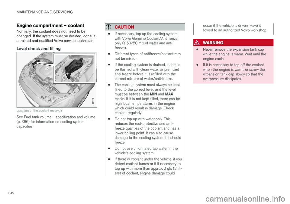
Location of the coolant reservoir
See Fuel tank volume – specification and volume (p. 386) for information on cooling systemcapacities.
CAUTION
• If necessary, top up the cooling system with Volvo Genuine Coolant/Antifreezeonly (a 50/50 mix of water and anti-freeze).
• Different types of antifreeze/coolant maynot be mixed.
• If the cooling system is drained, it shouldbe flushed with clean water or premixedanti-freeze before it is refilled with thecorrect mixture of water/anti-freeze.
• The cooling system must always be keptfilled to the correct level, and the level must be between the
MIN and MAX
marks. If it is not kept filled, there can be high local temperatures in the enginewhich could result in damage. Checkcoolant regularly!
• Do not top up with water only. Thisreduces the rust-protective and anti-freeze qualities of the coolant and has alower boiling point. It can also causedamage to the cooling system if it shouldfreeze.
• Do not use chlorinated tap water in thevehicle's cooling system.
• If there is coolant under the vehicle, if youdetect coolant fumes or if it necessary totop up with more than approx. 2 qts (2 lit-ers) of coolant, engine damage could
occur if the vehicle is driven. Have it towed to an authorized Volvo workshop.
WARNING
• Never remove the expansion tank cap while the engine is warm. Wait until theengine cools.
• If it is necessary to top off the coolantwhen the engine is warm, unscrew theexpansion tank cap slowly so that theoverpressure dissipates.
Page 345 of 404

MAINTENANCE AND SERVICING
}}
343
Engine compartment – brake fluid
The brake fluid should always be between the MIN and MAX marks on the inside of the reser-
voir.
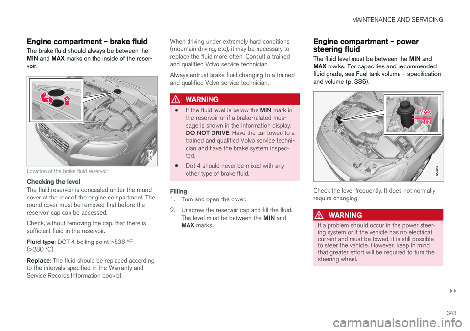
Location of the brake fluid reservoir
Checking the level
The fluid reservoir is concealed under the round cover at the rear of the engine compartment. Theround cover must be removed first before thereservoir cap can be accessed. Check, without removing the cap, that there is sufficient fluid in the reservoir. Fluid type : DOT 4 boiling point >536 °F
(>280 °C).Replace : The fluid should be replaced according
to the intervals specified in the Warranty and Service Records Information booklet. When driving under extremely hard conditions(mountain driving, etc), it may be necessary toreplace the fluid more often. Consult a trainedand qualified Volvo service technician. Always entrust brake fluid changing to a trained and qualified Volvo service technician.
WARNING
•
If the fluid level is below the
MIN mark in
the reservoir or if a brake-related mes- sage is shown in the information display: DO NOT DRIVE . Have the car towed to a
trained and qualified Volvo service techni- cian and have the brake system inspec-ted.
• Dot 4 should never be mixed with anyother type of brake fluid.
Filling
1. Turn and open the cover.
2. Unscrew the reservoir cap and fill the fluid.
The level must be between the MIN and
MAX marks.
Engine compartment – power steering fluid
The fluid level must be between the MIN and
MAX marks. For capacities and recommended
fluid grade, see Fuel tank volume – specification and volume (p. 386).
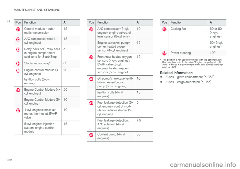
Check the level frequently. It does not normally require changing.
WARNING
If a problem should occur in the power steer- ing system or if the vehicle has no electricalcurrent and must be towed, it is still possibleto steer the vehicle. However, keep in mindthat greater effort will be required to turn thesteering wheel.
Page 364 of 404

||
MAINTENANCE AND SERVICING
362
PosFunction A
Control module - auto- matic transmission15
A/C compressor (not 4- cyl. engines)15
Relay-coils A/C, relay coils in engine compartmentcold zone for Start/Stop5
Starter motor relay
A
30
Engine control module (4- cyl. engines) Ignition coils (5-cyl. engine) 20
Engine Control Module (4- cyl. engines)
20
Engine Control Module (5-cyl. engine) 10
4-cyl. engines: mass air meter, thermostat, EVAPvalve10
5-cyl. engine: Injectionsystem, engine controlmodule 15
Pos
Function A
A/C compressor (5-cyl. engine), engine valves, oillevel sensor (5-cyl. only)10
Engine valves/oil pump/center heated oxygensensor (4-cyl. engines) 15
Front/rear heated oxygen sensors (4-cyl. engines),EVAP valve (5-cyl.engine), heated oxygensensors (5-cyl. engine)15
Oil pump/crankcase venti- lation heater/coolantpump (5-cyl. engines)
10
Ignition coils (4-cyl.engines) 15
Fuel leakage detection (5- cyl. engine), control mod-ule for radiator shutter (5-cyl. engine)5
Fuel leakage detection,A/C solenoid (4-cyl.engines) 7.5
Coolant pump (4-cyl. engines)
50
Pos
Function A
Cooling fan 60 or 80
(4-cyl. engines) 60 (5-cyl. engines)
Power steering 100
AThis position is not used on vehicles with the optional Start/ Stop function, refer to the table "Engine compartment coldzone" in Fuses – engine compartment cold zone (Start/Stoponly) (p. 367).
Related information
• Fuses – glove compartment (p. 363)
• Fuses – cargo area/trunk (p. 366)
Page 366 of 404

||
MAINTENANCE AND SERVICING
* Option/accessory.
364
Pos Function A
Controls in left rear passenger's door20
Keyless drive
* 7.5
Power driver's seat
*20
Power front passenger's seat
*20
-
Infotainment system display 5
Infotainment system: amplifier, Sir- iusXM
™ satellite radio * 10
Sensus control module 15
Bluetooth hands-free system 5
-
Power moonroof
*
Courtesy lighting, climate system sensor 5
12-volt sockets in tunnel console 15
Heated rear seat
* (passenger's
side) 15
Heated rear seat
* (driver's side) 15
Pos
Function A
-
Heated front passenger's seat*15
Heated driver's seat
*15
Park assist
*
Blind Spot Information System (BLIS) *, park assist camera *5
All Wheel Drive
* control module 15
Active chassis system
*10
Positions: fusebox B
Pos
Function A
Tailgate wiper 15
-
Front courtesy lighting, driver's door power window controls, power seat(s)*, 7.5
Instrument panel 5
Adaptive cruise control/collision warning
* 10
Pos
Function A
Courtesy lighting, rain sensor*,
HomeLInk ®
Wireless Control Sys-
tem * 7.5
Steering wheel module 7.5
Cental locking: fuel filler door 10
Electrically heated steering wheel
*15
Electrically heated windshield
*15
Tailgate unlock 10
Electrical folding rear seat out- board head restraints
*10
Fuel pump 20
Climate system control panel 5
-
Alarm, On-board diagnostic sys- tem
5
Satellite radio
*, audio system
amplifier 10
Airbag system, occupant weight sensor
10
Collision warning system
*5