2018 VOLVO V60 CROSS COUNTRY fuel
[x] Cancel search: fuelPage 74 of 404

||
INSTRUMENTS AND CONTROLS
* Option/accessory.
72
Gauges and indicators: digital instrument panel *
Different themes (display alternatives) can be selected for the digital instrument panel:
• Elegance
• Eco
• Performance
To change themes, press the OK button on the
left steering wheel lever and use the thumb wheel to scroll to
Themes. Press OK to confirm
your choice.
Theme Elegance : gauges and indicators
Fuel gauge. When the indicator shows one white marking, a yellow indicator light will illu-minate to indicate a low fuel level. See alsoTrip computer – introduction (p. 118) and Refueling – fuel requirements (p. 286) foradditional information.
Coolant temperature gauge
Speedometer
Tachometer (engine speed in thousands of revolutions per minute (rpm))
Gear indicator: Shows the currently selected gear
Theme
Eco: gauges and indicators
Fuel gauge. When the indicator shows a white marking, a yellow indicator light will illu-minate to indicate a low fuel level. See alsoTrip computer – introduction (p. 118) andRefueling – fuel requirements (p. 286) foradditional information.
Eco Guide (see Eco Guide * and Power
Meter * (p. 74))
Speedometer
Tachometer (engine speed in thousands of revolutions per minute (rpm))
Gear indicator: Shows the currently selected gear
Theme Performance : gauges and indicators
Fuel gauge. When the indicator shows a white marking, a yellow indicator light will illu-minate to indicate a low fuel level. See alsoTrip computer – introduction (p. 118) andRefueling – fuel requirements (p. 286) foradditional information.
Coolant temperature gauge
Speedometer
Tachometer (shows engine speed in thou- sands of revolutions per minute (rpm))
Page 77 of 404

INSTRUMENTS AND CONTROLS
}}
* Option/accessory.75
Utilized power
The larger, lower indicator shows the amount of engine power that has been utilized 2
. The higher
the reading on the scale, the greater the amount of power that is being utilized. The larger the gap between the two indicators, the greater the amount of power remaining.Information displays – indicator symbols
The indicator symbols alert the driver when cer- tain functions are activated, that a system isactively working or that a fault may have occur-red in a system or function.
Symbol Description
Fault in the Active Bending Light (ABL)*system
Malfunction indicator light
Anti-lock brake system (ABS)
Rear fog lights on
Stability system
The stability system's Sport mode is activated
Low fuel level
Information symbol, read the text displayed in the instrument panel
High beam indicator
Symbol Description
Left turn signal indicator
Right turn signal indicator
Tire pressure monitoring sensor (TPMS)A
The Eco function is on.
TheStart/Stop function is active (the engine has auto-stopped)
A
Option in Canada
Fault in the Active Bending Light (ABL)
system
This symbol will illuminate if there is a fault in the ABL system. See Active Bending Lights (ABL) *
(p. 95) for more information about this system.
2 Depending on rpm
Page 78 of 404

||
INSTRUMENTS AND CONTROLS
* Option/accessory.
76
Malfunction Indicator Light
As you drive, a computer called On-Board Diag- nostics II (OBDII) monitors your vehicle's engine,transmission, electrical and emission systems. The malfunction indicator light will illuminate if the computer senses a condition that potentiallymay need correcting. When this happens, pleasehave your vehicle checked by a trained and quali-fied Volvo service technician as soon as possible. A malfunction indicator light may have many cau- ses. Sometimes, you may not notice a change inyour car's behavior. Even so, an uncorrected con-dition could hurt fuel economy, emission controls,and drivability. Extended driving without correct-ing the cause could even damage other compo-nents in your vehicle. This light may illuminate if the fuel filler cap is not closed tightly or if the engine was running whilethe vehicle was refueled.
Anti-lock Brake System (ABS)
If the warning light comes on, there may be a malfunction in the ABS system (the standardbraking system will still function). Check the sys-tem by:
1. Stopping in a safe place and switching off
the ignition.
2. Restart the engine.
3. If the warning light goes off, no further action is required. If the indicator light remains on, the vehicle should be driven to a trained and qualified Volvoservice technician for inspection, see Brakes –general (p. 277) for additional information.
Rear fog lights
This symbol indicates that the rear fog lights are on.
Stability system
This indicator symbol flashes when the stability system is actively working to stabilize the vehicle,see Stability system – introduction (p. 174) formore detailed information.
Stability system - Sport mode
This symbol illuminates to indicate that the stabil- ity system's
Sport mode has been activated to
help provide maximum tractive force, for example when driving with snow chains, or driving in deepsnow or loose sand.
Low fuel level
When this light comes on, the vehicle should be refueled as soon as possible. See Refueling –fuel requirements (p. 286) for information aboutfuel and refueling.
Information symbol
The information symbol lights up and a text mes- sage is displayed to provide the driver with nec-essary information about one of the vehicle's sys-tems. The message can be erased and the sym- bol can be turned off by pressing the OK button
(see Information display – menu controls (p. 116) for information) or this will take place automatically after a short time (the length oftime varies, depending on the function affected). The information symbol may also illuminate together with other symbols.
High beam indicator
This symbol illuminates when the high beam headlights are on, or if the high beam flash func-tion is used.
Left turn signal indicator Right turn signal indicator
NOTE
•
Both turn signal indicators will flash when the hazard warning flashers are used.
• If either of these indicators flash fasterthan normal, the direction indicators arenot functioning properly.
Tire pressure monitoring system (TPMS)
*
This symbol illuminates to indicate that tire pres- sure in one or more tires is low, see Tire PressureMonitoring System (TPMS) – general information(p. 320) for detailed information.
Eco* function on
The symbol will illuminate when the Eco function is activated.
Start/stop *
The symbol illuminates when the engine has auto-stopped.
Page 123 of 404
INSTRUMENTS AND CONTROLS
}}
121
FunctionDescription
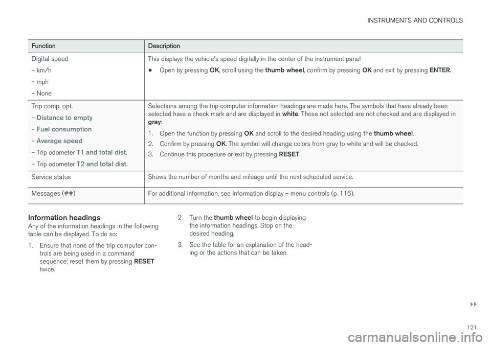
Digital speed – km/h – mph– None This displays the vehicle's speed digitally in the center of the instrument panel •
Open by pressing
OK, scroll using the thumb wheel, confirm by pressing OK and exit by pressing ENTER.
Trip comp. opt. –
Distance to empty
– Fuel consumption
– Average speed
– Trip odometer T1 and total dist.
– Trip odometer T2 and total dist.
Selections among the trip computer information headings are made here. The symbols that have already been selected have a check mark and are displayed in white. Those not selected are not checked and are displayed in
gray :
1. Open the function by pressing OK and scroll to the desired heading using the thumb wheel.
2. Confirm by pressing OK. The symbol will change colors from gray to white and will be checked.
3. Continue this procedure or exit by pressing RESET.
Service status Shows the number of months and mileage until the next scheduled service.
Messages (##) For additional information, see Information display – menu controls (p. 116).
Information headingsAny of the information headings in the following table can be displayed. To do so:
1. Ensure that none of the trip computer con-
trols are being used in a command sequence; reset them by pressing RESET
twice. 2.
Turn the thumb wheel to begin displaying
the information headings. Stop on the desired heading.
3. See the table for an explanation of the head- ing or the actions that can be taken.
Page 124 of 404
||
INSTRUMENTS AND CONTROLS
122
Information headings in the instrument panelDescription
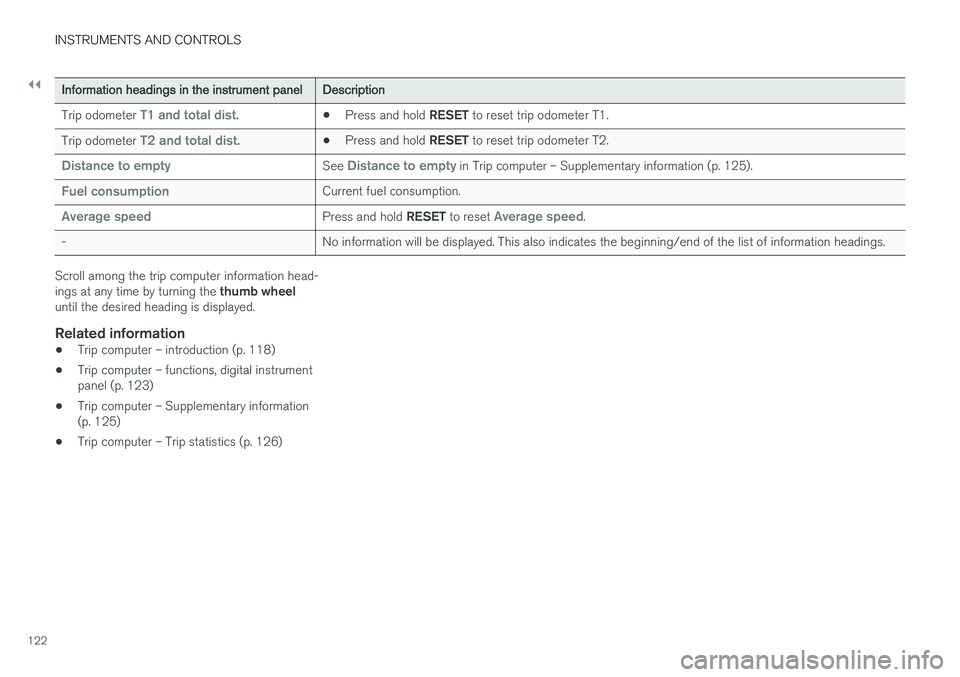
Trip odometer
T1 and total dist.• Press and hold
RESET to reset trip odometer T1.
Trip odometer
T2 and total dist.• Press and hold
RESET to reset trip odometer T2.
Distance to emptySee Distance to empty in Trip computer – Supplementary information (p. 125).
Fuel consumptionCurrent fuel consumption.
Average speedPress and hold RESET to reset Average speed.
- No information will be displayed. This also indicates the beginning/end of the list of information headings.
Scroll among the trip computer information head- ings at any time by turning the thumb wheel
until the desired heading is displayed.
Related information
• Trip computer – introduction (p. 118)
• Trip computer – functions, digital instrument panel (p. 123)
• Trip computer – Supplementary information(p. 125)
• Trip computer – Trip statistics (p. 126)
Page 125 of 404
INSTRUMENTS AND CONTROLS
}}
* Option/accessory.123
Trip computer – functions, digital instrument panel
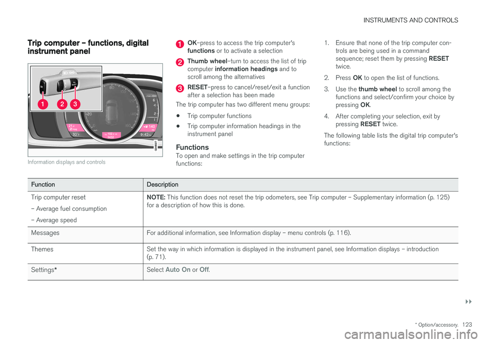
Information displays and controls
OK–press to access the trip computer's
functions or to activate a selection
Thumb wheel –turn to access the list of trip
computer information headings and to
scroll among the alternatives
RESET –press to cancel/reset/exit a function
after a selection has been made
The trip computer has two different menu groups: • Trip computer functions
• Trip computer information headings in the instrument panel
FunctionsTo open and make settings in the trip computerfunctions: 1. Ensure that none of the trip computer con-
trols are being used in a command sequence; reset them by pressing RESET
twice.
2. Press OK to open the list of functions.
3. Use the thumb wheel to scroll among the
functions and select/confirm your choice bypressing OK.
4. After completing your selection, exit by pressing RESET twice.
The following table lists the digital trip computer's functions:
Function Description
Trip computer reset – Average fuel consumption – Average speed NOTE:
This function does not reset the trip odometers, see Trip computer – Supplementary information (p. 125)
for a description of how this is done.
Messages For additional information, see Information display – menu controls (p. 116).
Themes Set the way in which information is displayed in the instrument panel, see Information displays – introduction (p. 71).
Settings * Select
Auto On or Off.
Page 126 of 404
||
INSTRUMENTS AND CONTROLS
124
FunctionDescription
Contrast mode /Color mode Adjust the instrument panel's contrast and color.
Service status Shows the number of months and mileage until the next scheduled service.
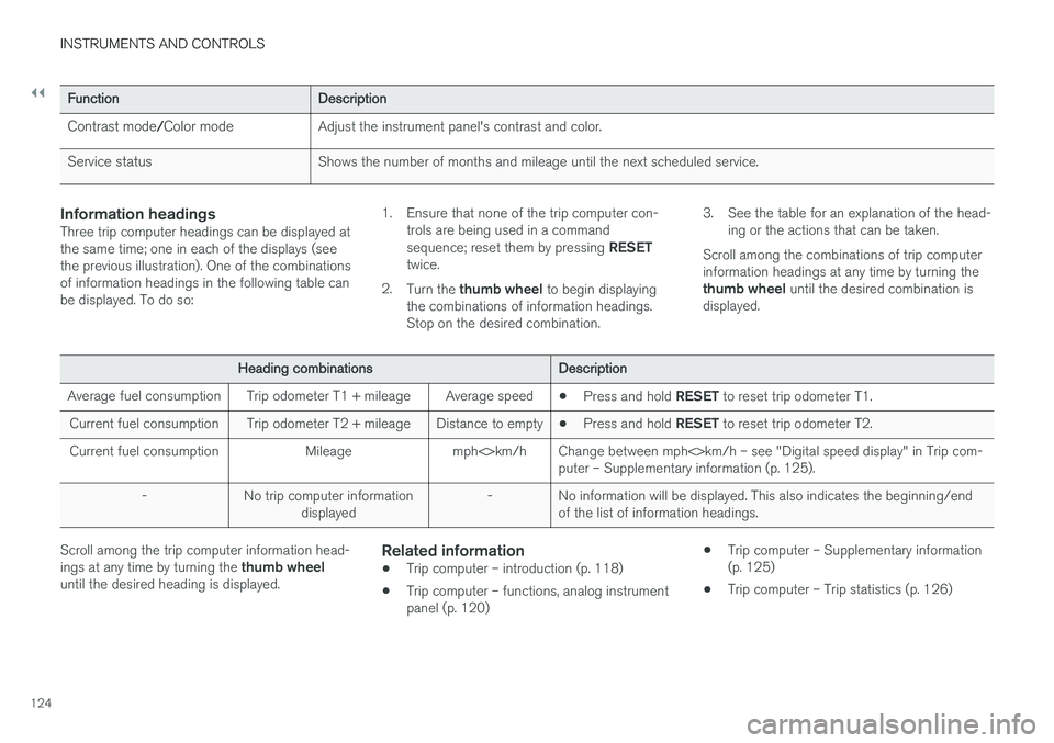
Information headingsThree trip computer headings can be displayed at the same time; one in each of the displays (seethe previous illustration). One of the combinationsof information headings in the following table canbe displayed. To do so: 1. Ensure that none of the trip computer con-
trols are being used in a command sequence; reset them by pressing RESET
twice.
2. Turn the thumb wheel to begin displaying
the combinations of information headings. Stop on the desired combination. 3. See the table for an explanation of the head-
ing or the actions that can be taken.
Scroll among the combinations of trip computerinformation headings at any time by turning the thumb wheel until the desired combination is
displayed.
Heading combinations Description
Average fuel consumption Trip odometer T1 + mileage Average speed •Press and hold
RESET to reset trip odometer T1.
Current fuel consumption Trip odometer T2 + mileage Distance to empty •Press and hold
RESET to reset trip odometer T2.
Current fuel consumption Mileage mph<>km/h Change between mph<>km/h – see "Digital speed display" in Trip com- puter – Supplementary information (p. 125).
- No trip computer information displayed - No information will be displayed. This also indicates the beginning/end
of the list of information headings.
Scroll among the trip computer information head- ings at any time by turning the thumb wheel
until the desired heading is displayed.Related information
• Trip computer – introduction (p. 118)
• Trip computer – functions, analog instrument panel (p. 120) •
Trip computer – Supplementary information(p. 125)
• Trip computer – Trip statistics (p. 126)
Page 127 of 404
INSTRUMENTS AND CONTROLS
* Option/accessory.125
Trip computer – Supplementary information
General information for both Analog and Digital trip computer functions.
Average fuel consumptionFuel consumption since the last time this func- tion was reset.
Average speedThe vehicle's average speed since the last timethis function was reset.
Current fuel consumptionCurrent fuel consumption is calculated approxi-mately once a second. When the vehicle is mov-ing at low speed, fuel consumption is displayedper unit of time. At higher speeds, it is displayedin terms of distance. Miles or kilometers can be displayed, see the heading "Changing units".
Distance to emptyThis function shows the approximate distancethat can be driven on the fuel remaining in the tank. When
Distance to empty shows "----",
there is very little useable fuel remaining in that tank; refuel as soon as possible. The calculationis based on average fuel consumption during thelast 20 miles (30 km) of driving and the amountof fuel remaining in the tank (the accuracy of thisfigure may vary if your driving style changes). An economical driving style will generally increasethis distance. See Economical driving (p. 291) for information about driving economically.
Digital speed display
*Speed is expressed in the unit not used by theinstrument panel's speedometer e.g., if the nor-mal speedometer is in mph, the trip computer willdisplay in the speed in km/h and vice versa.
Resetting an analog instrument panel
Trip odometer(s) and average speed
1. Display trip odometer T1 or T1, or Average
speed.
2. Press and hold RESET until selected func-
tion is reset.
Each trip computer heading must be reset indi- vidually.
Resetting a digital instrument panel
Trip odometer
1. Turn the thumb wheel to select the combi-
nation of headings containing the trip odom- eter to be reset.
2. Press and hold RESET until selected trip
odometer is reset.
Average speed and fuel consumption
1. Select Trip computer reset and press OK. 2. Select one of the following alternatives using
the thumb wheel and press OK:
• mpg
• mph
• Reset both
3. Finish by pressing RESET.
Changing unitsTo change the unit (miles/km) used to measure distance and speed, go to
MY CARSettings
System optionsDistance and fuel units.
NOTE
In addition to changing units in the trip com- puter, this also changes the units used in the Volvo Navigation System (VNS) *.
Related information
• Trip computer – introduction (p. 118)
• Trip computer – functions, analog instrument panel (p. 120)
• Trip computer – functions, digital instrumentpanel (p. 123)
• Trip computer – Trip statistics (p. 126)