2018 VOLVO V60 CROSS COUNTRY ECU
[x] Cancel search: ECUPage 115 of 404
INSTRUMENTS AND CONTROLS
}}
* Option/accessory.113
Retain the original transmitter of the RF device you are programming for use in other vehicles aswell as for future HomeLink programming. It isalso suggested that upon the sale of the vehicle,the programmed HomeLink buttons be erasedfor security purposes. Refer to “Resetting Home- Link Buttons” in HomeLink
®
Wireless Control
System * – programming (p. 113).
Using HomeLinkTo operate, simply press and hold the pro- grammed HomeLink button until the traineddevice begins to operate (this may take severalseconds). Activation will now occur for the traineddevice (i.e., garage door opener, gate operator,security system, entry door lock, home/officelighting, etc.). For convenience, the hand-heldtransmitter of the device may also be used at anytime. In the event that there are still programmingdifficulties or questions, contact HomeLink at:www.homelink.com/www.youtube.com/HomeLinkGentex or by phoning the hotline at 1–800–355–3515.
NOTE
If the ignition is switched off, HomeLink will function for 30 minutes after the driver's doorhas been opened.
HomeLink ®
Wireless Control
System * – programming
The HomeLink Wireless Control System pro- vides a convenient way to replace up to threehand-held radio-frequency (RF) transmittersused to activate devices such as gate operators,garage door openers, entry door locks, securitysystems, even home lighting. Additional informa-tion can be found on the Internetatwww.homelink.com/www.youtube.com/HomeLinkGentex or by phoning the hotline at 1–800–355–3515.
NOTE
Some vehicles may require the ignition to be switched on or be in the “accessories” posi-tion for programming and/or operation ofHomeLink. It is also recommended that a newbattery be placed in the hand-held transmitterof the device being programmed to Home-Link for quicker training and accurate trans-mission of the radio-frequency signal. TheHomeLink buttons must be reset first. Whenthis has been completed, Homelink is inlearning mode so that you can perform pro-gramming.
1. Position the end of your hand-held transmit- ter 1–3 inches (5–14 cm) away from the HomeLink button you wish to program whilekeeping the indicator light in view. 2. Simultaneously press and hold both the
chosen HomeLink and hand-held transmitterbuttons until the HomeLink indicator lightchanges from a slow to a rapidly blinkinglight. Now you may release both the Home-Link and hand-held transmitter buttons.
NOTE
Some devices may require you to replace this Programming Step 2 with procedures notedin the “Gate Operator / Canadian Program-ming” section. If the HomeLink indicator lightdoes not change to a rapidly blinking lightafter performing these steps, contact Home-Link at www.homelink.com/www.youtube.com/HomeLinkGentex or byphoning the hotline at 1–800–355–3515.
Page 148 of 404

LOADING AND STORAGE
146
Loading – general
The load carrying capacity of your vehicle is determined by factors such as the number ofpassengers, the amount of cargo, the weight ofany accessories that may be installed, etc.
To increase loading space, the rear seat back- rests can be folded down, see Rear seats – fold-
ing backrest (p. 89).
When loading the cargo area, keep the following
in mind:
• Load objects in the cargo area against thebackrest whenever possible.
• Unstable loads can be secured to the loadanchoring eyelets with straps or web lash-ings to help keep them from shifting.
• Stop the engine and apply the parking brakewhen loading or unloading long objects. Thegear selector can be knocked out of positionby long loads, which could set the vehicle inmotion.
WARNING
• Stop the engine, put the gear selector in P
, and apply the parking brake when
loading or unloading long objects.
• The vehicle's driving characteristics may change depending on the weight and dis-tribution of the load.
• A 44-pound (20 kg) object produces aforce of 2,200 pounds (1,000 kg) in ahead-on collision at 30 mph (50 km/h).
• The cargo compartment and rear seatshould not be loaded to a level higherthan 2 in. (5 cm) below the upper edge ofthe rear side windows. Objects placedhigher than this level could impede thefunction of the Inflatable Curtain.
Related information
• Load anchoring eyelets (p. 147)
• Steel cargo grid (p. 150)
• Loading – roof load carriers (p. 146)
Loading – roof load carriers
Using load carriersLoad carriers are available as Volvo accessories. Observe the following points when in use:
• To avoid damaging your vehicle and toachieve maximum safety when driving, werecommend using the load carriers that Volvohas developed especially for your vehicle.
• Volvo-approved removable roof racks aredesigned to carry the maximum allowableroof load for this vehicle: 220 lbs (100 kg).For non-Volvo roof racks, check the manu-facturer's weight limits for the rack.
• Never exceed the rack manufacturer's weighlimits and never exceed the maximum ratedroof load of 220 lbs (100 kg).
• Avoid single-point loads. Distribute loadsevenly.
• Place heavier cargo at the bottom of theload.
• Secure the cargo correctly with appropriatetie-down equipment.
• Check periodically that the load carriers andload are properly secured.
• Remember that the vehicle's center of gravityand handling change when you carry a loadon the roof.
Page 149 of 404

LOADING AND STORAGE
147
•
The vehicle's wind resistance and fuel con- sumption will increase with the size of theload.
• Drive smoothly. Avoid rapid starts, fast cor-nering and hard braking.
Related information
• Loading – general (p. 146)
• Load anchoring eyelets (p. 147)
Load anchoring eyelets
The load anchoring eyelets on both sides of the vehicle are used to fasten straps, etc., to helpanchor items in the cargo area.
WARNING
The two upper hooks shown in the illustration are for holding grocery bags only. They are not intended for anchoring heavy objects.
WARNING
• Cover sharp edges on long loads to help prevent injury to occupants. Secure theload to help prevent shifting during sud-den stops.
• Always secure large and heavy objectswith a seat belt or cargo retaining straps.
• Always secure the load to help prevent itfrom moving in the event of sudden stops.
• Switch off the engine, apply the parking brake and put the gear selector in
P
when loading and unloading the vehicle.
Related information
• Loading – general (p. 146)
Page 150 of 404
LOADING AND STORAGE
148
Grocery bag holder
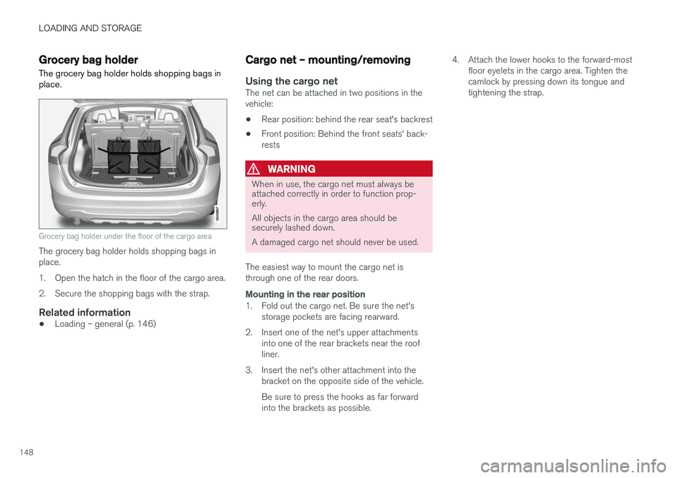
The grocery bag holder holds shopping bags in place.
Grocery bag holder under the floor of the cargo area
The grocery bag holder holds shopping bags in place.
1. Open the hatch in the floor of the cargo area.
2. Secure the shopping bags with the strap.
Related information
• Loading – general (p. 146)
Cargo net – mounting/removing
Using the cargo netThe net can be attached in two positions in the vehicle:
• Rear position: behind the rear seat's backrest
• Front position: Behind the front seats' back-rests
WARNING
When in use, the cargo net must always be attached correctly in order to function prop-erly. All objects in the cargo area should be securely lashed down. A damaged cargo net should never be used.
The easiest way to mount the cargo net is through one of the rear doors.
Mounting in the rear position
1. Fold out the cargo net. Be sure the net's storage pockets are facing rearward.
2. Insert one of the net's upper attachments into one of the rear brackets near the roof liner.
3. Insert the net's other attachment into the bracket on the opposite side of the vehicle. Be sure to press the hooks as far forward into the brackets as possible. 4. Attach the lower hooks to the forward-most
floor eyelets in the cargo area. Tighten thecamlock by pressing down its tongue andtightening the strap.
Page 152 of 404
||
LOADING AND STORAGE
1503. Press both sides of the cover until they click
into place
. The red mark will no longer be
visible.
4. Check that both ends of the cover are securely locked in place.
Removing the cover1. Press one of the end pieces of the coverinward.
2. Pull the cover carefully upward and outward. The other end will release automatically from its retaining bracket.
Folding down the cargo area cover's rear flap
The cargo area cover's rear flap points horizon- tally when the cover is retracted (rolled up). Tofold it down:
–Pull the flap slightly rearward past its sup- ports and fold it down.
NOTE
On models equipped with this cover, it should be removed before a child seat is attached tothe child restraint anchors.
Related information
• Loading – general (p. 146)
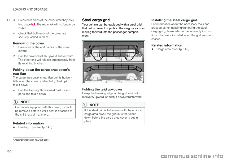
Steel cargo grid
Your vehicle can be equipped with a steel grid that helps prevent objects in the cargo area frommoving forward into the passenger compart-ment.
Folding the grid up/downGrasp the lowering edge of the grid and pull it rearward/upward, or push it downward/forward.
NOTE
If the steel grid is to be used with the optional cargo area cover, the grid must be foldeddown before the cargo area cover is put inplace.
Installing the steel cargo gridFor information about the necessary tools and procedures for installing/removing the steelcargo grid, please refer to the assembly instruc- tions 1
that were included when the grid was pur-
chased.
Related information
• Cargo area cover (p. 149)
1
Assembly instruction no. 30756681.
Page 176 of 404
DRIVER SUPPORT
174
Stability system – introduction The Electronic Stability Control (ESC) system consists of a number of functions designed tohelp reduce wheel spin, counteract skidding andto generally help improve directional stability.
A pulsating sound will be audible when the system is actively operating and isnormal. Acceleration will also beslightly slower than normal.
WARNING
•The stability system (ESC) is intended to help improve driving safety but cannotdeal with all situations, or traffic, road andweather conditions. Speed and drivingstyle should always be adapted to thecurrent driving situation.
• ESC supplements, but can never replace,the driver's judgment and responsibilitywhen operating the vehicle. The driver isalways responsible for operating the vehi-cle in a safe manner in accordance withapplicable traffic regulations.
ESC consists of the following functions:
• Traction control
• Spin control
• Active Yaw Control
• Engine Drag Control •
Corner Traction Control
Traction Control (TC)
This function is designed to help reduce wheel spin at low speeds by transferring power from adrive wheel that begins to lose traction to thewheel on the opposite side of the vehicle (on thesame axle).
Spin Control (SC)
The SC function is designed to help prevent the drive wheels from spinning while the vehicle isaccelerating.
Active Yaw Control (AYC)
This function helps maintain directional stability, for example when cornering, by braking one ormore of the wheels if the vehicle shows a ten-dency to skid or slide laterally.
Corner Traction Control (CTC)
CTC compensates for understeering and helps provide additional stability when acceleratingthrough a curve by preventing the inside wheelfrom spinning. This is particularly useful whenaccelerating on a curving highway on-ramp. CTC is most effective if the stability system's Sport
mode is selected. See the section about
Sport mode.
Engine Drag Control (EDC)
EDC helps keep the engine running if the wheels show a tendency to lock, e.g., when shifting downin the Geartronic manual shifting mode or whileusing the engine's braking function on a slipperysurface. If the engine were to stop, power steer- ing would not function, making the vehicle moredifficult to steer.
Trailer Stability Assist (TSA)
The TSA helps stabilize a vehicle that is towing a trailer when the vehicle and trailer have begun tosway. See Trailer Stability Assist (TSA) (p. 294)for more information. This system is automatically deactivated if the driver selects
Sport mode.
Related information
•Stability system – operation (p. 175)
• Stability system – symbols and messages (p. 176)
• Trailer Stability Assist (TSA) (p. 294)
Page 195 of 404
DRIVER SUPPORT
}}
193
Radar sensor
The radar sensor is designed to help detect cars or larger vehicles driving in the same direction asyour vehicle, in the same lane.
The radar sensor and its limitationsIn addition to being used by the Adaptive Cruise Control (ACC), the radar sensor is also used byDistance Alert (see Distance Alert – introduction(p. 198)) and Collision Warning with Full Auto-brake and Pedestrian Detection (see Collisionwarning – introduction (p. 209)).
WARNING
• If there is visible damage to the front grille or you suspect that the radar sensormay be damaged in any way, contact atrained and qualified Volvo service techni-cian as soon as possible. The radar sen-sor may only function partially (or not atall) if it is damaged or is not securely fas-tened in place.
• Accessories or other objects, such asextra headlights, must not be installed infront of the grille.
• Modification of the radar sensor couldmake its use illegal.
The radar sensor's capacity to detect vehiclesahead is impeded: •
if the radar sensor is obstructed and cannotdetect other vehicles, for example in heavyrain, or if snow or other objects are obscuringthe radar sensor.
NOTE
Keep the area in front of the radar sensor clean.
•
if the speed of vehicles ahead is significantly different from your own speed.
Related information
•Adaptive Cruise Control – introduction(p. 183)
• Collision warning – introduction (p. 209)
• Distance Alert – introduction (p. 198)
Adaptive Cruise Control – limitations
The ACC cannot cover all driving situations and traffic, weather and road conditions.
Situations where ACC may not function optimally
WARNING
• The radar sensor has a limited field of vision. In some situations it may detect avehicle later than expected or not detectother vehicles at all.
• If ACC is not functioning properly, cruisecontrol will also be disabled.
Page 258 of 404
||
DRIVER SUPPORT
* Option/accessory.
256 The BLIS/CTA
18
sensors are located on the
inside of the rear fenders/bumper. The surfaces in front of the sensors must be kept clean for the system to function optimally.
CAUTION
Repairs to the BLIS/CTA systems and/or repainting the rear bumper should only bedone by a trained and qualified Volvo servicetechnician.
Related information
• BLIS
* – introduction (p. 251)
• BLIS
* – function (p. 252)
• BLIS
* – operation (p. 253)
• BLIS
* – Cross Traffic Alert (CTA) (p. 254)
• BLIS
* – messages (p. 256)
BLIS * – messages
If BLIS/CTA 19
are not functioning normally, a
symbol will illuminate in the instrument panel and a text message will be displayed. Follow anyinstructions that may be provided. These messages include:
Message System status
CTA OFFCTA has been switched off manually. BLIS remains active.
BLIS and CTA OFFTrailerattachedBLIS and CTA are temporarily deactivated because a trailer'swiring has been connected tothe vehicle's electrical system.
BLIS and CTA ServicerequiredBLIS and CTA are not func- tioning normally.
• If this message recurs,the systems should beinspected by a trainedand qualified Volvo serv-ice technician.
Messages can be erased by pressing the
OK
button on the left steering wheel lever.
Related information
• BLIS
* – introduction (p. 251)
• BLIS
* – function (p. 252)
• BLIS
* – operation (p. 253)
• BLIS
* – Cross Traffic Alert (CTA) (p. 254)
• BLIS
* – limitations (p. 255)
18
Cross Traffic Alert
19 Cross Traffic Alert