2018 VOLVO V60 CROSS COUNTRY warning
[x] Cancel search: warningPage 298 of 404

||
STARTING AND DRIVING
296
Attaching the towing eyeletThe towing eyelet is located under the floor of the cargo area, with the spare tire. Thiseyelet must be screwed into the positionsprovided on the right sides of either the frontor rear bumper (see illustration).
There are two different types of covers over the openings for the towing eyelet and theyhave to be opened differently.
• If the cover has a notch, insert a coin, etc.,into the notch and pry open the edge ofthe cover. Open the cover completely andremove it.
• If the cover has a mark along one edge orin a corner, press the mark while pryingout the opposite side/corner using a coin,etc. Open the cover and remove it.
Screw the towing eyelet in place, first by handand then using the tire iron until it is securely inplace. After the vehicle has been towed, the eyelet should be removed and returned to its storagelocation. Press the cover for the attachment point back into position.
WARNING
• When the vehicle is being towed, the igni- tion should be in mode
II (in mode I, all of
the vehicle's airbags are deactivated). For more information, see Ignition modes(p. 82)
• Never remove the remote key from theignition slot when the vehicle is beingtowed. For vehicles with keyless drive, theremote key must remain inside the vehi-cle.
• The power brakes and power steering willnot function when the engine is not run-ning. Approximately 5 times more pres-sure will be required on the brake pedaland the steering wheel will be considera-bly harder to turn.
• The towing eyelets must not be used forpulling the vehicle out of a ditch or forany similar purpose involving severestrain.
Related information
•Towing the vehicle (p. 295)
• Towing by tow truck (p. 296)
Towing by tow truck
When necessary, call for professional help from an authorized towing company. Volvo recom-mends the use of flat bed equipment.
CAUTION
In certain conditions, the towing eyelet may be used to pull the vehicle onto aflatbed tow truck.
• The vehicle's position and ground clear-ance determine if it can be pulled up ontoa flatbed tow truck using the towing eye-let.
• If the angle of the tow truck
Page 303 of 404
WHEELS AND TIRES
301
Tires – storage and ageWhen storing complete wheels (tires mounted on rims), they should be suspended off the flooror placed on their sides on the floor.
New Tires
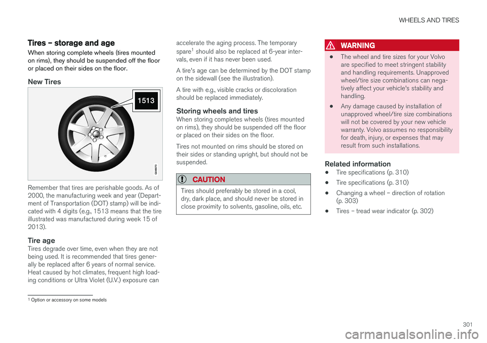
Remember that tires are perishable goods. As of 2000, the manufacturing week and year (Depart-ment of Transportation (DOT) stamp) will be indi-cated with 4 digits (e.g., 1513 means that the tireillustrated was manufactured during week 15 of2013).
Tire ageTires degrade over time, even when they are not being used. It is recommended that tires gener-ally be replaced after 6 years of normal service.Heat caused by hot climates, frequent high load-ing conditions or Ultra Violet (U.V.) exposure can accelerate the aging process. The temporary spare
1
should also be replaced at 6-year inter-
vals, even if it has never been used. A tire's age can be determined by the DOT stamp on the sidewall (see the illustration). A tire with e.g., visible cracks or discoloration should be replaced immediately.
Storing wheels and tiresWhen storing completes wheels (tires mountedon rims), they should be suspended off the flooror placed on their sides on the floor. Tires not mounted on rims should be stored on their sides or standing upright, but should not besuspended.
CAUTION
Tires should preferably be stored in a cool, dry, dark place, and should never be stored inclose proximity to solvents, gasoline, oils, etc.
WARNING
• The wheel and tire sizes for your Volvo are specified to meet stringent stabilityand handling requirements. Unapprovedwheel/tire size combinations can nega-tively affect your vehicle's stability andhandling.
• Any damage caused by installation ofunapproved wheel/tire size combinationswill not be covered by your new vehiclewarranty. Volvo assumes no responsibilityfor death, injury, or expenses that mayresult from such installations.
Related information
•Tire specifications (p. 310)
• Tire specifications (p. 310)
• Changing a wheel – direction of rotation(p. 303)
• Tires – tread wear indicator (p. 302)
1
Option or accessory on some models
Page 307 of 404

WHEELS AND TIRES
305
7. There are two jack attachment points on
each side of the vehicle. Position the jack under the attachment point to be used on alevel, firm, non-slippery surface and crank itup until it is correctly aligned and seated inthe attachment point. Before raising the vehi-cle, check that the jack is still correctly posi-tioned in the attachment.
8. Raise the vehicle until the wheel to be changed is lifted off the ground.
9. Unscrew the wheel nuts completely and remove the wheel.
WARNING
• The jack must correctly engage the jack attachment.
• Be sure the jack is on a firm, level, non-slippery surface.
• Never allow any part of your body to beextended under a vehicle supported by ajack.
• Use the jack intended for the vehiclewhen changing a tire. For any other job,use stands to support the vehicle.
• Apply the parking brake and put the gear selector in the Park (
P) position.
• Block the wheels standing on the ground, use rigid wooden blocks or large stones.
• The jack should be kept well-greased andclean, and should not be damaged.
• No objects should be placed between thebase of jack and the ground, or betweenthe jack and the attachment bar on thevehicle.
NOTE
The jack provided with your vehicle is intended to be used only in temporary situa-tions such as changing wheels in the event ofa flat tire. Only the jack that came with yourparticular model should be used to lift thevehicle. If the vehicle needs to be lifted morefrequently or for a prolonged period, using agarage jack or hoist is recommended. Alwaysfollow this device
Page 308 of 404
WHEELS AND TIRES
* Option/accessory.
306
Changing a wheel – spare wheel Wheel changes should always be carried out correctly.
Spare tireA spare tire can be purchased for your vehicle as an accessory. Follow the instructions includedwith the spare tire regarding use and stowing inthe vehicle. See also Changing a wheel – remov-ing wheel (p. 303) for additional information.
Spare wheelThe following instructions only apply if you have purchased a temporary spare wheel * for your
vehicle. If there is no temporary spare wheel in your vehi- cle, please see Tire sealing system * – general
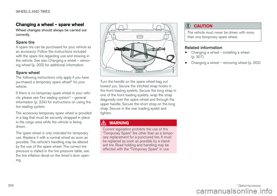
information (p. 324) for instructions on using the tire sealing system. The accessory temporary spare wheel is provided in a bag that must be securely strapped in placein the cargo area while the vehicle is beingdriven. The spare wheel is only intended for temporary use. Replace it with a normal wheel as soon aspossible. The vehicle's handling may be alteredby the use of the spare wheel. The correct tirepressure is stated in the tire pressure table, seethe tire inflation decal on the driver's door open-ing.Turn the handle on the spare wheel bag out toward you. Secure the stitched strap hooks inthe front loading eyelets. Secure the long strap inone of the front loading eyelets, wrap the strapdiagonally over the spare wheel and through theupper handle. Secure the short strap on the longstrap. Secure in the rear loading eyelet andtighten.
WARNING
Current legislation prohibits the use of the “Temporary Spare” tire other than as a tempo-rary replacement for a punctured tire. It mustbe replaced as soon as possible by a stand-ard tire. Road holding and handling may beaffected with the “Temporary Spare” in use.
CAUTION
The vehicle must never be driven with more than one temporary spare wheel.
Related information
• Changing a wheel – installing a wheel (p. 307)
• Changing a wheel – removing wheel (p. 303)
Page 309 of 404
WHEELS AND TIRES
}}
* Option/accessory.307
Changing a wheel – accessing the spare wheel
The following procedure explains how to access the spare wheel (where applicable).
1. Release the bag's retaining straps.
2. Lift the bag out of the vehicle and remove the spare wheel from the bag.
3. Fold up the floor hatch in the cargo area.4. Remove the jack * and tools * from the foam
block and change the wheels (see the instructions in the following section "Chang-ing a wheel").
5. After changing wheels, return the jack and tools to the foam block and close the floorhatch.
6. If possible, place the wheel with the punc- tured tire in the bag. 7. If there is a wheel in the bag, strap the bag
securely in place in the cargo area.
WARNING
•If there is a wheel in the bag, the bag must be securely restrained using its straps andthe load anchoring eyelets in the cargoarea. See (p. 306) and carefully follow theinstructions.
• If the wheel with the punctured tire is toobig to fit in the bag, it should be securelyrestrained in the cargo area using suitablestraps, a net for anchoring cargo, etc.
Changing a wheel – installing a wheel
It is important to re-install wheels properly.
Re-installing the wheel1. Clean the contact surfaces on the wheel and hub.
2. Lift the wheel and place it on the hub.
Tighten the wheel nuts
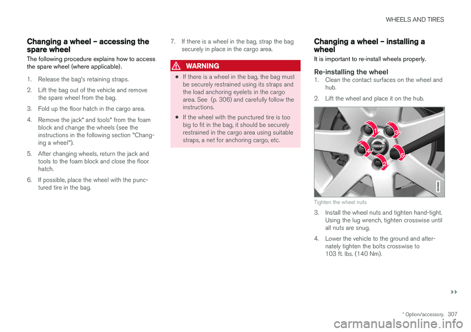
3. Install the wheel nuts and tighten hand-tight. Using the lug wrench, tighten crosswise until all nuts are snug.
4. Lower the vehicle to the ground and alter- nately tighten the bolts crosswise to103 ft. lbs. (140 Nm).
Page 311 of 404
WHEELS AND TIRES
}}}}
309
WARNING
•Under-inflation is the most common cause of tire failure and may result insevere tire cracking, tread separation, or"blow-out," with unexpected loss of vehi-cle control and increased risk of injury.
• Under-inflated tires reduce the load car-rying capacity of your vehicle.
When weather temperature changes occur, tireinflation pressures also change. A 10-degreetemperature drop causes a corresponding dropof 1 psi (7 kPa) in inflation pressure. Check yourtire pressures frequently and adjust them to theproper pressure, which can be found on the vehi-cle's tire information placard or certification label.
Related information
• Tire specifications (p. 310)
• Tires – storage and age (p. 301)
• Tires – tread wear indicator (p. 302)
Tire inflation – checking pressure
Inflation pressure should be checked when the tires are cold.
Cold tires
The tires are considered to be cold when they have the same temperature as the sur-rounding (ambient) air. This temperature is normally reached after the vehicle has been parked for at least 3 hours. After driving a distance of approximately 1 mile (1.6 km), the tires are considered to be hot. If youhave to drive farther than this distance to pumpyour tire(s), check and record the tire pressurefirst and add the appropriate air pressure whenyou get to the pump. If checking tire pressure when the tire is hot, never "bleed" or reduce air pressure. The tiresare hot from driving and it is normal for pressuresto increase above recommended cold pressures.A hot tire at or below recommended cold inflationpressure could be significantly under-inflated.
To check inflation pressure:
1. Remove the cap from the valve on one tire, then firmly press the tire gauge onto the valve.
2. Add air to reach the recommended air pres- sure. 3. Replace the valve cap.
CAUTION
•
After inflating the tires, always reinstall the valve cap to help avoid damage to thevalve from dirt, gravel, etc.
• Use plastic valve caps only. Metal capscould corrode and become difficult toremove.
4. Visually inspect the tires to make sure there
are no nails or other objects embedded that could puncture the tire and cause an air leak.
5. Check the sidewalls to make sure there are no gouges, cuts, bulges or other irregulari-ties.
6. Repeat this procedure for each tire, including the spare 3
.
NOTE
• If you overfill the tire, release air by push- ing on the metal stem in the center of thevalve. Then recheck the pressure withyour tire gauge.
• Some spare tires (available as an acces-sory) require higher inflation pressurethan the other tires. Consult the tire infla-
3
Available as an accessory
Page 315 of 404

WHEELS AND TIRES
}}
313
6. If your vehicle will be towing a trailer, load
from your trailer will be transferred to your vehicle. Consult this manual to determinehow this reduces the available cargo and lug-gage load capacity of your vehicle.
WARNING
• Exceeding the permissible axle weight, gross vehicle weight, or any other weightrating limits can cause tire overheatingresulting in permanent deformation orcatastrophic failure.
• Do not use replacement tires with lowerload carrying capacities than the tires thatwere original equipment on the vehiclebecause this will lower the vehicle's GVWrating. Use only tires with the correct loadcarrying capacity. Consult your Volvoretailer for information.
Tire specifications – terminology
The following is a glossary of tire-related terms.
The tire suppliers may have additional markings, notes or warnings such as standard load, radialtubeless, etc.
• Tire information placard
: A placard show-
ing the OE (Original Equipment) tire sizes,recommended inflation pressure, and themaximum weight the vehicle can carry.
• Tire Identification Number (TIN)
: A number
on the sidewall of each tire providing infor-mation about the tire brand and manufactur-ing plant, tire size and date of manufacturer.
• Inflation pressure
: A measure of the
amount of air in a tire.
• Standard load
: A class of P-metric or Metric
tires designed to carry a maximum load at35 psi [37 psi (2.5 bar) for Metric tires].Increasing the inflation pressure beyond thispressure will not increase the tires load car-rying capability.
• Extra load
: A class of P-metric or Metric
tires designed to carry a heavier maximumload at 41 psi [43 psi (2.9 bar) for Metrictires]. Increasing the inflation pressurebeyond this pressure will not increase thetire's load carrying capability.
• kPa
: Kilopascal, a metric unit of air pressure.
• PSI
: Pounds per square inch, a standard unit
of air pressure. •
B-pillar
: The structural member at the side
of the vehicle behind the front door.
• Bead area of the tire
: Area of the tire next
to the rim.
• Sidewall of the tire
: Area between the bead
area and the tread.
• Tread area of the tire
: Area of the perime-
ter of the tire that contacts the road whenmounted on the vehicle.
• Rim
: The metal support (wheel) for a tire or a
tire and tube assembly upon which the tirebeads are seated.
• Maximum load rating
: a figure indicating
the maximum load in pounds and kilogramsthat can be carried by the tire. This rating isestablished by the tire manufacturer.
• Maximum permissible inflation pressure
:
the greatest amount of air pressure thatshould ever be put in the tire. This limit is setby the tire manufacturer.
• Recommended tire inflation pressure
:
inflation pressure, established by Volvo,which is based on the type of tires that aremounted on a vehicle at the factory. Thisinformation can be found on the tire inflationplacard(s) located on the driver's side B-pillarand in the tire inflation table in this chapter.
• Cold tires
: The tires are considered to be
cold when they have the same temperatureas the surrounding (ambient) air. This tem-
Page 316 of 404
WHEELS AND TIRES
314perature is normally reached after the vehicle has been parked for at least 3 hours.
Tire specifications – Uniform Tire Quality Grading ALL PASSENGER VEHICLE TIRES MUST CONFORM TO FEDERAL SAFETY REQUIRE-MENTS IN ADDITION TO THESE GRADES
.
Quality grades can be found, where applica- ble, on the tire sidewall between the treadshoulder and maximum section width. Forexample: Treadwear 200 Traction AA Temperature A
TREADWEARThe treadwear grade is a comparative rating based on the wear rate of the tire when testedunder controlled conditions on a specified gov-ernment test course. For example, a tire graded150 would wear one and one half (1 ½) times aswell on the government course as a tire graded100. The relative performance of tires dependsupon the actual conditions of their use, however,and many depart significantly from the norm dueto variation in driving habits, maintenance practi-ces and differences in road characteristics andclimate.
TRACTIONThe traction grades, from highest to lowest, areAA, A, B, and C, as measured under controlledconditions on specified government test surfacesof asphalt and concrete. A tire marked C mayhave poor traction performance. The traction grade assigned to this tire is based on braking(straight-ahead) traction tests and is not a meas-ure of cornering (turning) traction.
WARNING
The traction grade assigned to this tire is based on braking (straight-ahead) tractiontests and is not a measure of cornering (turn-ing) traction.
TEMPERATUREThe temperature grades are A (the highest), B, and C, representing the tire's resistance to thegeneration of heat and its ability to dissipate heatwhen tested under controlled conditions on aspecified indoor laboratory test wheel. Sustainedhigh temperature can cause the material of thetire to degenerate and reduce tire life, and exces-sive temperature can lead to sudden tire failure.The grade C corresponds to a minimum level ofperformance that all passenger vehicle tires mustmeet under the Federal Motor Safety StandardNo. 109. Grades B and A represent higher levelsof performance on the laboratory test wheel thanthe minimum required by law.