2018 VOLVO S60 INSCRIPTION ECU
[x] Cancel search: ECUPage 141 of 396

LOADING AND STORAGE
}}
139
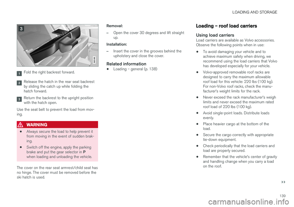
Fold the right backrest forward.
Release the hatch in the rear seat backrest by sliding the catch up while folding thehatch forward.
Return the backrest to the upright position with the hatch open.
Use the seat belt to prevent the load from mov-ing.
WARNING
• Always secure the load to help prevent it from moving in the event of sudden brak-ing.
• Switch off the engine, apply the parking brake and put the gear selector in
P
when loading and unloading the vehicle.
The cover on the rear seat armrest/child seat has no hinge. The cover must be removed before theski hatch is used. Removal:
–Open the cover 30 degrees and lift straight up.
Installation:
–Insert the cover in the grooves behind the upholstery and close the cover.
Related information
• Loading – general (p. 138)
Loading – roof load carriers
Using load carriersLoad carriers are available as Volvo accessories. Observe the following points when in use:
• To avoid damaging your vehicle and toachieve maximum safety when driving, werecommend using the load carriers that Volvohas developed especially for your vehicle.
• Volvo-approved removable roof racks aredesigned to carry the maximum allowableroof load for this vehicle: 220 lbs (100 kg).For non-Volvo roof racks, check the manu-facturer's weight limits for the rack.
• Never exceed the rack manufacturer's weighlimits and never exceed the maximum ratedroof load of 220 lbs (100 kg).
• Avoid single-point loads. Distribute loadsevenly.
• Place heavier cargo at the bottom of theload.
• Secure the cargo correctly with appropriatetie-down equipment.
• Check periodically that the load carriers andload are properly secured.
• Remember that the vehicle's center of gravityand handling change when you carry a loadon the roof.
Page 142 of 396

||
LOADING AND STORAGE
140•
The vehicle's wind resistance and fuel con- sumption will increase with the size of theload.
• Drive smoothly. Avoid rapid starts, fast cor-nering and hard braking.
Related information
• Loading – general (p. 138)
• Load anchoring eyelets (p. 140)
Load anchoring eyelets
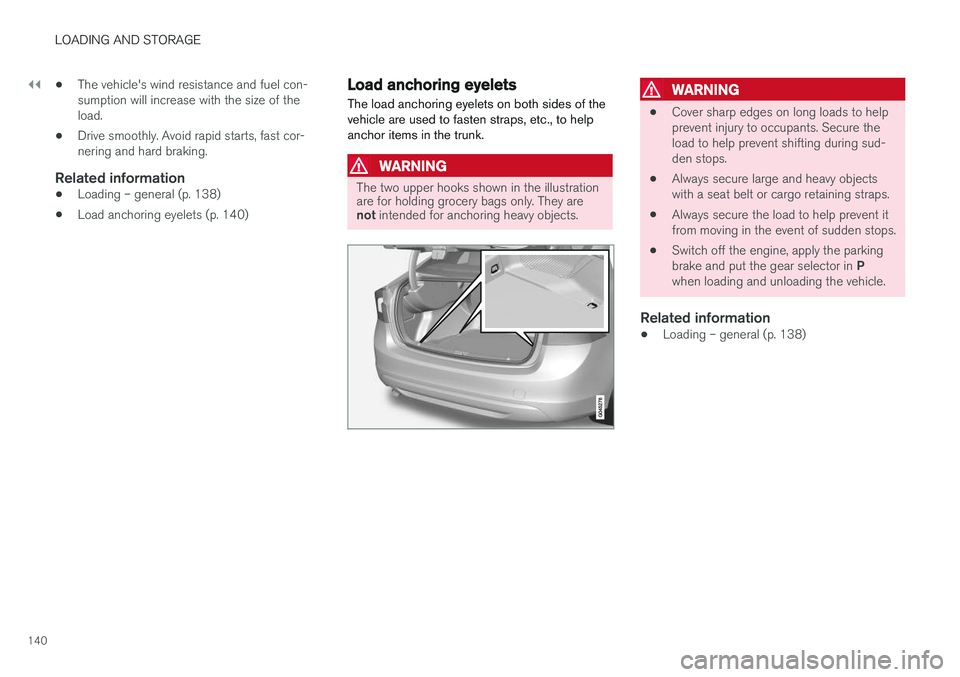
The load anchoring eyelets on both sides of the vehicle are used to fasten straps, etc., to helpanchor items in the trunk.
WARNING
The two upper hooks shown in the illustration are for holding grocery bags only. They are not intended for anchoring heavy objects.
WARNING
• Cover sharp edges on long loads to help prevent injury to occupants. Secure theload to help prevent shifting during sud-den stops.
• Always secure large and heavy objectswith a seat belt or cargo retaining straps.
• Always secure the load to help prevent itfrom moving in the event of sudden stops.
• Switch off the engine, apply the parking brake and put the gear selector in
P
when loading and unloading the vehicle.
Related information
• Loading – general (p. 138)
Page 143 of 396

LOADING AND STORAGE
141
Grocery bag holder
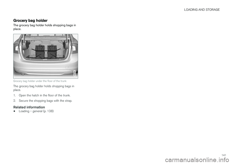
The grocery bag holder holds shopping bags in place.
Grocery bag holder under the floor of the trunk
The grocery bag holder holds shopping bags in place.
1. Open the hatch in the floor of the trunk.
2. Secure the shopping bags with the strap.
Related information
• Loading – general (p. 138)
Page 168 of 396

DRIVER SUPPORT
166
Stability system – introduction The Electronic Stability Control (ESC) system consists of a number of functions designed tohelp reduce wheel spin, counteract skidding andto generally help improve directional stability.
A pulsating sound will be audible when the system is actively operating and isnormal. Acceleration will also beslightly slower than normal.
WARNING
•The stability system (ESC) is intended to help improve driving safety but cannotdeal with all situations, or traffic, road andweather conditions. Speed and drivingstyle should always be adapted to thecurrent driving situation.
• ESC supplements, but can never replace,the driver's judgment and responsibilitywhen operating the vehicle. The driver isalways responsible for operating the vehi-cle in a safe manner in accordance withapplicable traffic regulations.
ESC consists of the following functions:
• Traction control
• Spin control
• Active Yaw Control
• Engine Drag Control •
Corner Traction Control
Traction Control (TC)
This function is designed to help reduce wheel spin at low speeds by transferring power from adrive wheel that begins to lose traction to thewheel on the opposite side of the vehicle (on thesame axle).
Spin Control (SC)
The SC function is designed to help prevent the drive wheels from spinning while the vehicle isaccelerating.
Active Yaw Control (AYC)
This function helps maintain directional stability, for example when cornering, by braking one ormore of the wheels if the vehicle shows a ten-dency to skid or slide laterally.
Corner Traction Control (CTC)
CTC compensates for understeering and helps provide additional stability when acceleratingthrough a curve by preventing the inside wheelfrom spinning. This is particularly useful whenaccelerating on a curving highway on-ramp. CTC is most effective if the stability system's Sport
mode is selected. See the section about
Sport mode.
Engine Drag Control (EDC)
EDC helps keep the engine running if the wheels show a tendency to lock, e.g., when shifting downin the Geartronic manual shifting mode or whileusing the engine's braking function on a slipperysurface. If the engine were to stop, power steer- ing would not function, making the vehicle moredifficult to steer.
Trailer Stability Assist (TSA)
The TSA helps stabilize a vehicle that is towing a trailer when the vehicle and trailer have begun tosway. See Trailer Stability Assist (TSA) (p. 285)for more information. This system is automatically deactivated if the driver selects
Sport mode.
Related information
•Stability system – operation (p. 167)
• Stability system – symbols and messages (p. 168)
• Trailer Stability Assist (TSA) (p. 285)
Page 187 of 396

DRIVER SUPPORT
}}
185
Radar sensor
The radar sensor is designed to help detect cars or larger vehicles driving in the same direction asyour vehicle, in the same lane.
The radar sensor and its limitationsIn addition to being used by the Adaptive Cruise Control (ACC), the radar sensor is also used byDistance Alert (see Distance Alert – introduction(p. 190)) and Collision Warning with Full Auto-brake and Pedestrian Detection (see Collisionwarning – introduction (p. 201)).
WARNING
• If there is visible damage to the front grille or you suspect that the radar sensormay be damaged in any way, contact atrained and qualified Volvo service techni-cian as soon as possible. The radar sen-sor may only function partially (or not atall) if it is damaged or is not securely fas-tened in place.
• Accessories or other objects, such asextra headlights, must not be installed infront of the grille.
• Modification of the radar sensor couldmake its use illegal.
The radar sensor's capacity to detect vehiclesahead is impeded: •
if the radar sensor is obstructed and cannotdetect other vehicles, for example in heavyrain, or if snow or other objects are obscuringthe radar sensor.
NOTE
Keep the area in front of the radar sensor clean.
•
if the speed of vehicles ahead is significantly different from your own speed.
Related information
•Adaptive Cruise Control – introduction(p. 175)
• Collision warning – introduction (p. 201)
• Distance Alert – introduction (p. 190)
Adaptive Cruise Control – limitations
The ACC cannot cover all driving situations and traffic, weather and road conditions.
Situations where ACC may not function optimally
WARNING
• The radar sensor has a limited field of vision. In some situations it may detect avehicle later than expected or not detectother vehicles at all.
• If ACC is not functioning properly, cruisecontrol will also be disabled.
Page 250 of 396

||
DRIVER SUPPORT
* Option/accessory.
248 The BLIS/CTA
18
sensors are located on the
inside of the rear fenders/bumper. The surfaces in front of the sensors must be kept clean for the system to function optimally.
CAUTION
Repairs to the BLIS/CTA systems and/or repainting the rear bumper should only bedone by a trained and qualified Volvo servicetechnician.
Related information
• BLIS
* – introduction (p. 243)
• BLIS
* – function (p. 244)
• BLIS
* – operation (p. 245)
• BLIS
* – Cross Traffic Alert (CTA) (p. 246)
• BLIS
* – messages (p. 248)
BLIS * – messages
If BLIS/CTA 19
are not functioning normally, a
symbol will illuminate in the instrument panel and a text message will be displayed. Follow anyinstructions that may be provided. These messages include:
Message System status
CTA OFFCTA has been switched off manually. BLIS remains active.
BLIS and CTA OFFTrailerattachedBLIS and CTA are temporarily deactivated because a trailer'swiring has been connected tothe vehicle's electrical system.
BLIS and CTA ServicerequiredBLIS and CTA are not func- tioning normally.
• If this message recurs,the systems should beinspected by a trainedand qualified Volvo serv-ice technician.
Messages can be erased by pressing the
OK
button on the left steering wheel lever.
Related information
• BLIS
* – introduction (p. 243)
• BLIS
* – function (p. 244)
• BLIS
* – operation (p. 245)
• BLIS
* – Cross Traffic Alert (CTA) (p. 246)
• BLIS
* – limitations (p. 247)
18
Cross Traffic Alert
19 Cross Traffic Alert
Page 252 of 396

STARTING AND DRIVING
* Option/accessory.
250
Starting the engine
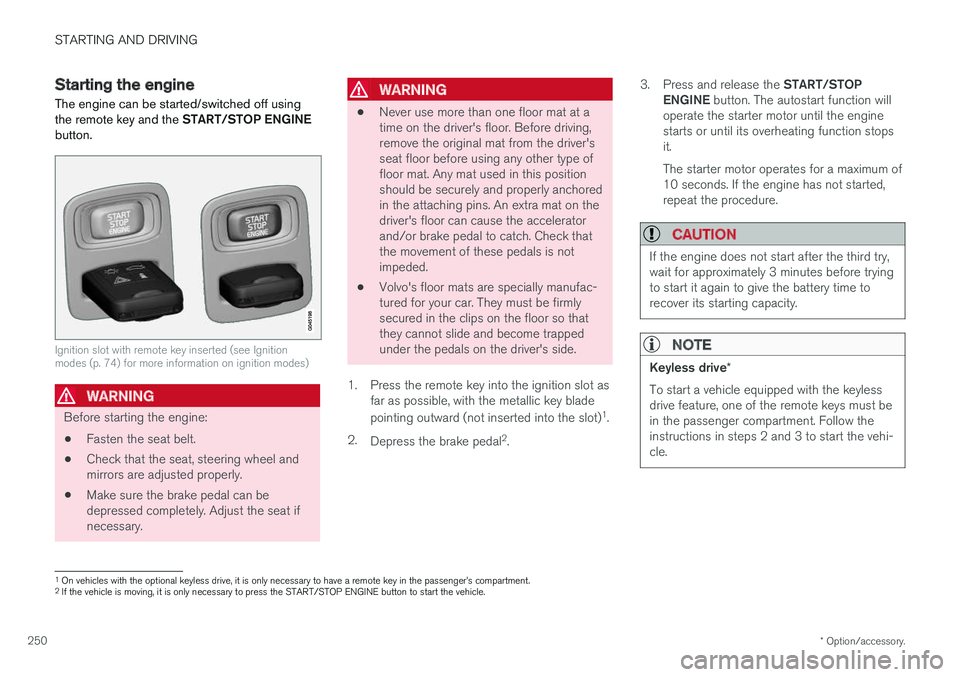
The engine can be started/switched off using the remote key and the START/STOP ENGINE
button.
Ignition slot with remote key inserted (see Ignition modes (p. 74) for more information on ignition modes)
WARNING
Before starting the engine:
• Fasten the seat belt.
• Check that the seat, steering wheel and mirrors are adjusted properly.
• Make sure the brake pedal can bedepressed completely. Adjust the seat ifnecessary.
WARNING
•Never use more than one floor mat at a time on the driver's floor. Before driving,remove the original mat from the driver'sseat floor before using any other type offloor mat. Any mat used in this positionshould be securely and properly anchoredin the attaching pins. An extra mat on thedriver's floor can cause the acceleratorand/or brake pedal to catch. Check thatthe movement of these pedals is notimpeded.
• Volvo's floor mats are specially manufac-tured for your car. They must be firmlysecured in the clips on the floor so thatthey cannot slide and become trappedunder the pedals on the driver's side.
1. Press the remote key into the ignition slot as far as possible, with the metallic key blade pointing outward (not inserted into the slot) 1
.
2. Depress the brake pedal 2
. 3.
Press and release the START/STOP
ENGINE button. The autostart function will
operate the starter motor until the engine starts or until its overheating function stopsit. The starter motor operates for a maximum of 10 seconds. If the engine has not started,repeat the procedure.
CAUTION
If the engine does not start after the third try, wait for approximately 3 minutes before tryingto start it again to give the battery time torecover its starting capacity.
NOTE
Keyless drive *
To start a vehicle equipped with the keyless drive feature, one of the remote keys must bein the passenger compartment. Follow theinstructions in steps 2 and 3 to start the vehi-cle.
1 On vehicles with the optional keyless drive, it is only necessary to have a remote key in the passenger
Page 273 of 396

STARTING AND DRIVING
}}
271
Parking brake – general information The electric parking brake helps to keep the vehicle stationary when it is parked.
Electric parking brake
Parking brake control
NOTE
•A faint sound from the parking brake's electric motor can be heard when theparking brake is being applied. Thissound can also be heard during the auto-matic function check of the parkingbrake.
• The brake pedal will move slightly whenthe electric parking brake is applied orreleased.
Low battery voltageIf the battery voltage is too low, the parking brake cannot be applied or released.
Connect
an auxiliary battery if the battery voltage is toolow, see Jump starting (p. 254).
Parking on a hill
• If the vehicle is pointing uphill, turn the frontwheels so that they point away from the curb.
• If the vehicle is pointing downhill, turn thefront wheels so that they point toward thecurb.
The parking brake should also be applied.
Related information
• Parking brake – applying (p. 271)
• Parking brake – releasing (p. 272)
• Parking brake – symbols and messages(p. 274)
• Brakes – general (p. 267)
Parking brake – applying
Applying the electric parking brake
Parking brake control
1. Press firmly on the brake pedal. 2.Push the control. >
The
symbol in the instrument
panel flashes while the parking brake is being applied and glows steadily when theparking brake has been fully applied.
3. Release the brake pedal and ensure that the vehicle is at a standstill.
4. When the vehicle is parked, the gear selector must be in position P.