Page 289 of 396

STARTING AND DRIVING
}}
287
Attaching the towing eyeletThe towing eyelet is located under the floor of the trunk. This eyelet must be screwedinto the positions provided on the right sidesof either the front or rear bumper (see illus-tration).
There are two different types of covers over the openings for the towing eyelet and theyhave to be opened differently.
• If the cover has a notch, insert a coin, etc.,into the notch and pry open the edge ofthe cover. Open the cover completely andremove it.
• If the cover has a mark along one edge orin a corner, press the mark while pryingout the opposite side/corner using a coin,etc. Open the cover and remove it.
Screw the towing eyelet in place, first by handand then using the tire iron until it is securely inplace. After the vehicle has been towed, the eyelet should be removed and returned to its storagelocation. Press the cover for the attachment point back into position.
WARNING
• When the vehicle is being towed, the igni- tion should be in mode
II (in mode I, all of
the vehicle's airbags are deactivated). For more information, see Ignition modes(p. 74)
• Never remove the remote key from theignition slot when the vehicle is beingtowed. For vehicles with keyless drive, theremote key must remain inside the vehi-cle.
• The power brakes and power steering willnot function when the engine is not run-ning. Approximately 5 times more pres-sure will be required on the brake pedaland the steering wheel will be considera-bly harder to turn.
• The towing eyelets must not be used forpulling the vehicle out of a ditch or forany similar purpose involving severestrain.
Related information
•Towing the vehicle (p. 286)
• Towing by tow truck (p. 287)
Towing by tow truck
When necessary, call for professional help from an authorized towing company. Volvo recom-mends the use of flat bed equipment.
CAUTION
In certain conditions, the towing eyelet may be used to pull the vehicle onto aflatbed tow truck.
• The vehicle's position and ground clear-ance determine if it can be pulled up ontoa flatbed tow truck using the towing eye-let.
• If the angle of the tow truck
Page 295 of 396

WHEELS AND TIRES
}}
* Option/accessory.293
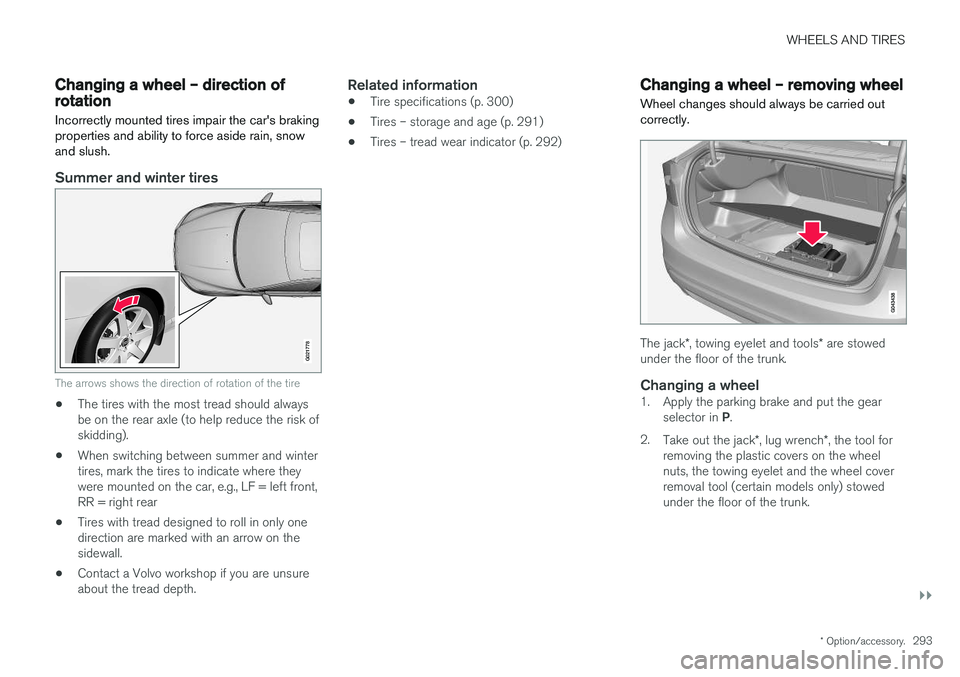
Changing a wheel – direction of rotation Incorrectly mounted tires impair the car's braking properties and ability to force aside rain, snowand slush.
Summer and winter tires
G021778
The arrows shows the direction of rotation of the tire
•The tires with the most tread should always be on the rear axle (to help reduce the risk ofskidding).
• When switching between summer and wintertires, mark the tires to indicate where theywere mounted on the car, e.g., LF = left front,RR = right rear
• Tires with tread designed to roll in only onedirection are marked with an arrow on thesidewall.
• Contact a Volvo workshop if you are unsureabout the tread depth.
Related information
•Tire specifications (p. 300)
• Tires – storage and age (p. 291)
• Tires – tread wear indicator (p. 292)
Changing a wheel – removing wheel Wheel changes should always be carried out correctly.
The jack
*, towing eyelet and tools * are stowed
under the floor of the trunk.
Changing a wheel1. Apply the parking brake and put the gear
selector in P.
2. Take out the jack *, lug wrench *, the tool for
removing the plastic covers on the wheel nuts, the towing eyelet and the wheel coverremoval tool (certain models only) stowedunder the floor of the trunk.
Page 297 of 396

WHEELS AND TIRES
295
7. There are two jack attachment points on
each side of the vehicle. Position the jack under the attachment point to be used on alevel, firm, non-slippery surface and crank itup until it is correctly aligned and seated inthe attachment point. Before raising the vehi-cle, check that the jack is still correctly posi-tioned in the attachment.
8. Raise the vehicle until the wheel to be changed is lifted off the ground.
9. Unscrew the wheel nuts completely and remove the wheel.
WARNING
• The jack must correctly engage the jack attachment.
• Be sure the jack is on a firm, level, non-slippery surface.
• Never allow any part of your body to beextended under a vehicle supported by ajack.
• Use the jack intended for the vehiclewhen changing a tire. For any other job,use stands to support the vehicle.
• Apply the parking brake and put the gear selector in the Park (
P) position.
• Block the wheels standing on the ground, use rigid wooden blocks or large stones.
• The jack should be kept well-greased andclean, and should not be damaged.
• No objects should be placed between thebase of jack and the ground, or betweenthe jack and the attachment bar on thevehicle.
NOTE
The jack provided with your vehicle is intended to be used only in temporary situa-tions such as changing wheels in the event ofa flat tire. Only the jack that came with yourparticular model should be used to lift thevehicle. If the vehicle needs to be lifted morefrequently or for a prolonged period, using agarage jack or hoist is recommended. Alwaysfollow this device
Page 307 of 396

WHEELS AND TIRES
305
WARNING
The temperature grade for this tire is estab- lished for a tire that is properly inflated andnot overloaded. Excessive speed, under-infla-tion, or excessive loading, either separately orin combination, can cause heat buildup andtire failure.
Snow chains
Snow chains can be used on your Volvo with the following restrictions:
• Snow chains should be installed on front wheels only. Use only Volvo approved snowchains.
• If accessory, aftermarket or "custom" tiresand wheels are installed and are of a size dif-ferent than the original tires and wheels,chains in some cases CANNOT be used.Sufficient clearances between chains andbrakes, suspension and body componentsmust be maintained.
• Some strap-on type chains will interfere withbrake components and therefore CANNOTbe used.
• All Wheel Drive models
: Snow chains
should only be installed on the front wheels.
• Certain size tires may not allow the assemblyof snow chains/traction devices.
Consult your Volvo retailer for additional snowchain information.
CAUTION
• Check local regulations regarding the use of snow chains before installing.
• Use single-sided snow chains only.
• Always follow the chain manufacturer'sinstallation instructions carefully. Installchains as tightly as possible andretighten periodically.
• Never exceed the chain manufacturer'sspecified maximum speed limit. (Underno circumstances should you exceed31 mph (50 km/h).
• Avoid bumps, holes or sharp turns whendriving with snow chains.
• The handling of the vehicle can beadversely affected when driving withchains. Avoid fast or sharp turns as wellas locked wheel braking.
Page 330 of 396

MAINTENANCE AND SERVICING
328
Engine compartment – overviewThe overview shows the main inspection points in the engine compartment.
Coolant expansion tank
Power steering fluid reservoir
Dipstick-engine oil
Filler cap-engine oil
Cover over brake fluid reservoir
Battery
Relay/fuse box
Washer fluid reservoir
Engine compartment - 4-cylinder engines only
Filler cap-engine oil
Coolant expansion tank
Radiator
Brake fluid reservoir
Battery
Relay/fuse box
Washer fluid reservoir
Air cleaner
The appearance of the engine compartment may vary depending on engine model.
WARNING
The cooling fan (located at the front of the engine compartment, behind the radiator) maystart or continue to operate (for up to6 minutes) after the engine has beenswitched off.
WARNING
Before performing any operations in the engine compartment, the ignition should always be completely switched off (in mode 0,
see Ignition modes (p. 74)) and there should be no remote keys in the passenger compart- ment. The gear selector should be in the P
(park) position. If the engine has been run- ning, wait until it has cooled before touchingany components in the engine compartment. The distributor ignition system operates at very high voltages. Special safety precautionsmust be followed to prevent injury. Alwaysturn the ignition off when:
• Replacing distributor ignition components e.g. plugs, coil, etc.
• Do not touch any part of the distributorignition system while the engine is run-ning. This may result in unintended move-ments and body injury.
Page 335 of 396

MAINTENANCE AND SERVICING
}}
333
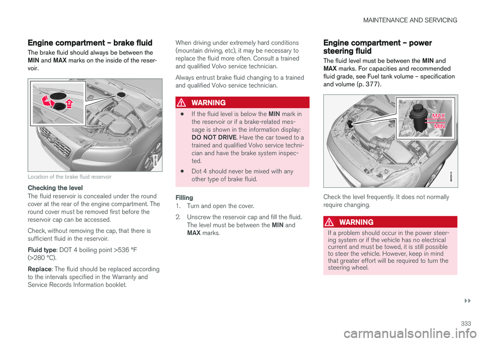
Engine compartment – brake fluid
The brake fluid should always be between the MIN and MAX marks on the inside of the reser-
voir.
Location of the brake fluid reservoir
Checking the level
The fluid reservoir is concealed under the round cover at the rear of the engine compartment. Theround cover must be removed first before thereservoir cap can be accessed. Check, without removing the cap, that there is sufficient fluid in the reservoir. Fluid type : DOT 4 boiling point >536 °F
(>280 °C).Replace : The fluid should be replaced according
to the intervals specified in the Warranty and Service Records Information booklet. When driving under extremely hard conditions(mountain driving, etc), it may be necessary toreplace the fluid more often. Consult a trainedand qualified Volvo service technician. Always entrust brake fluid changing to a trained and qualified Volvo service technician.
WARNING
•
If the fluid level is below the
MIN mark in
the reservoir or if a brake-related mes- sage is shown in the information display: DO NOT DRIVE . Have the car towed to a
trained and qualified Volvo service techni- cian and have the brake system inspec-ted.
• Dot 4 should never be mixed with anyother type of brake fluid.
Filling
1. Turn and open the cover.
2. Unscrew the reservoir cap and fill the fluid.
The level must be between the MIN and
MAX marks.
Engine compartment – power steering fluid
The fluid level must be between the MIN and
MAX marks. For capacities and recommended
fluid grade, see Fuel tank volume – specification and volume (p. 377).
Check the level frequently. It does not normally require changing.
WARNING
If a problem should occur in the power steer- ing system or if the vehicle has no electricalcurrent and must be towed, it is still possibleto steer the vehicle. However, keep in mindthat greater effort will be required to turn thesteering wheel.
Page 341 of 396
MAINTENANCE AND SERVICING
339
Related information
•Bulbs – specifications (p. 341)
Bulbs – location of taillight bulbs
The following illustrations show the location of the bulbs in the taillight cluster.
Taillight lens, right side
Brake light (LEDs)
Side marker light (LEDs)
Brake light
Parking light (LEDs)
Backup light
Turn signal
Rear fog light
Backup lights
1. Open the panel in the trunk.
2. Remove the bulb holder by turning it coun- terclockwise.
3. Remove the defective bulb by pressing it in slightly and turning it counterclockwise before pulling it out.
4. Insert a new bulb, press it in and turn it clockwise.
5. Reinsert the bulb holder by turning it clock- wise.
Related information
• Bulbs – introduction (p. 334)
• Bulbs – specifications (p. 341)
Page 344 of 396
||
MAINTENANCE AND SERVICING
342
Lighting functionWat-
tage Bulb
Backup light 21 H21W LL
Brake light 21 P21W LL
Trunk lighting 10 SV8.5 (length 38mm)
Front footwell lighting 3 W2, 1x9.5d
type T10
NOTE
Please consult a Volvo retailer