Page 228 of 576

228
YARIS iA_OM_OM99Q46z_(U)
3-13. Rear View Monitor
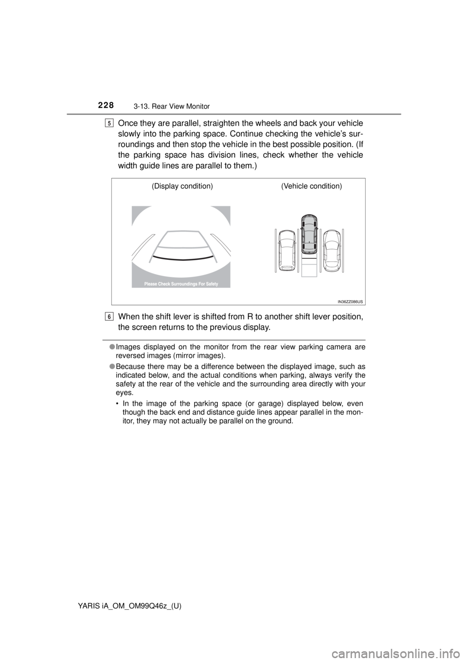
Once they are parallel, straighten the wheels and back your vehicle
slowly into the parking space. Continue checking the vehicle’s sur-
roundings and then stop the vehicle in the best possible position. (If
the parking space has division lines, check whether the vehicle
width guide lines are parallel to them.)
When the shift lever is shifted from R to another shift lever position,
the screen returns to the previous display.
● Images displayed on the monitor from the rear view parking camera are
reversed images (mirror images).
● Because there may be a difference between the displayed image, such as
indicated below, and the actual conditions when parking, always verify the
safety at the rear of the vehicle and the surrounding area directly with your
eyes.
• In the image of the parking space (or garage) displayed below, even
though the back end and distance guide lines appear parallel in the mon-
itor, they may not actually be parallel on the ground.
5
(Display condition) (Vehicle condition)
6
Page 229 of 576
YARIS iA_OM_OM99Q46z_(U)
2293-13. Rear View Monitor
3
When Driving
Some variance occurs between the actual road and the displayed
road. Such variance in distance perspective could lead to an accident.
Note the following conditions that may cause a variance in distance
perspective.
■When the vehicle is tilted due to the weight of passengers and
load
When the vehicle rear is lower ed, the object displayed on the
screen appears farther than the actual distance.
• When parking in a space with a divi-
sion line on only one side of the park-
ing space, the division line and the
vehicle width guide line may appear
parallel on the monitor, but they may
not actually be parallel on the ground.
Variance Between Actual Road Conditions and Displayed Image
Object
Variance
Page 439 of 576

439
YARIS iA_OM_OM99Q46z_(U)
5-3. Owner Maintenance
5
Maintenance and Care
Tires
Inspect all tire pressures monthly (including the spare) when the tires
are cold. Maintain recommended pressures for the best ride, han-
dling, and minimum tire wear.
Refer to the spec ification charts
(→P. 5 6 0).
With tire pressure monitoring system:
After adjusting the tire pressure, init ialization of the tire pressure mon-
itoring system is necessary to make the system operate normally.
Refer to Tire Pressure Monitoring System Initialization on P. 221.
For reasons of proper performance, safety, and better fuel econ-
omy, always maintain recommended tire inflation pressures and
stay within the recommended load limits and weight distribu-
tion.
WARNING
■Using Different Tire Types
Driving your vehicle with different ty pes of tires is dangerous. It could
cause poor handling and poor braking; leading to loss of control.
Except for the limited use of the temporary spare tire, use only the same
type tires (radial, bias-belted, bias-type) on all four wheels.
■Using Wrong-Sized Tires
Using any other tire size than what is specified for the vehicle (→P. 560)
is dangerous. It could seriously affect ride, handling, ground clearance,
tire clearance, and speedometer ca libration. This could cause you to
have an accident. Use only tires that are the correct size specified for
the vehicle.
Tire Inflation Pressure
Page 444 of 576
4445-3. Owner Maintenance
YARIS iA_OM_OM99Q46z_(U)
WARNING
■Always use wheels of the correct size on your vehicle
Using a wrong-sized wheel is dangerous. Braking and handling could
be affected, leading to loss of control and an accident.
NOTICE
A wrong-sized wheel may adversely affect:
●Tire fit
●Wheel and bearing life
●Ground clearance
●Snow-chain clearance
●Speedometer calibration
●Headlight aim
●Bumper height
●Tire Pressure Monitoring System (if equipped)
Page 480 of 576
4806-2. Flat Tire
YARIS iA_OM_OM99Q46z_(U)
NOTICE
●When using the temporary spare tire, driving stability may decrease
compared to when using only the conventional tire. Drive carefully.
●To avoid damage to the temporary s pare tire or to the vehicle, observe
the following precautions:
• Do not exceed 50 mph (80 km/h).
• Avoid driving over obstacles. Also, do not drive through an auto- matic car wash. This tire’s diameter is smaller than a conventional
tire, so the ground clearance is reduced.
• Do not use a tire chain on this ti re because it will not fit properly.
• Do not use your temporary spare tire on any other vehicle, it has been designed only for your Toyota.
• Use only one temporary spare tire on your vehicle at the same time.
Page 483 of 576
YARIS iA_OM_OM99Q46z_(U)
4836-2. Flat Tire
6
If Trouble Arises
If your vehicle is equipped with
a wheel cover, pry off the wheel
cover with the beveled end of
the jack lever.
Force the end of the jack lever
firmly between wheel and cover,
or removal will be difficult.
Loosen the lug nuts by turning
them counterclockwise one turn
each, but do not remove any
lug nuts until the tire has been
raised off the ground.
Place the jack on the ground.
Turn the jack screw in the direc-
tion shown in the figure and
adjust the jack head so that it is
close to the jack-up position.
Place the jack under the jack-
up position closest to the tire
being changed with the jack
head squarely under the jack-
up point.
Removing a Flat Tire
1
2
3
Jack head4
Jacking position
5
Page 491 of 576
491
YARIS iA_OM_OM99Q46z_(U)
6-3. Battery Runs Out
6
If Trouble Arises
Jump-Starting
Jump-starting is dangerous if done incorrectly. So follow the proce-
dure carefully. If you feel unsure about jump-starting, we strongly rec-
ommend that you have a competent service technician do the work.Remove the battery cover.
Make sure the booster battery is 12 V and that its negative terminal
is grounded.
If the booster battery is in another vehicle, do not allow both vehi-
cles to touch. Turn off the engine of the vehicle with the booster bat-
tery and all unnecessary electrical loads in both vehicles.
1
2
3
Page 492 of 576
4926-3. Battery Runs Out
YARIS iA_OM_OM99Q46z_(U)
Connect the jumper cables in the exact sequence as in the illustra-
tion.
Connect one end of a cable to the positive terminal on the dis-
charged battery.
Attach the other end to the positive terminal on the booster bat-
tery.
Connect one end of the other cabl e to the negative terminal of
the booster battery.
Connect the other end to the ground point indicated in the illus-
tration away from the discharged battery.
Start the engine of the booster v ehicle and run it a few minutes.
Then start the engine of the other vehicle.
When finished, carefully disconnect the cables in the reverse order
described in the illustration.
If the battery cover has been removed, install it in the reverse order
of removal.
Verify that the covers are securely installed.
4
Jumper cables
Booster battery
Discharged battery
1
2
3
4
5
6
7