2018 TOYOTA TUNDRA tow mirror
[x] Cancel search: tow mirrorPage 20 of 672
20Pictorial index
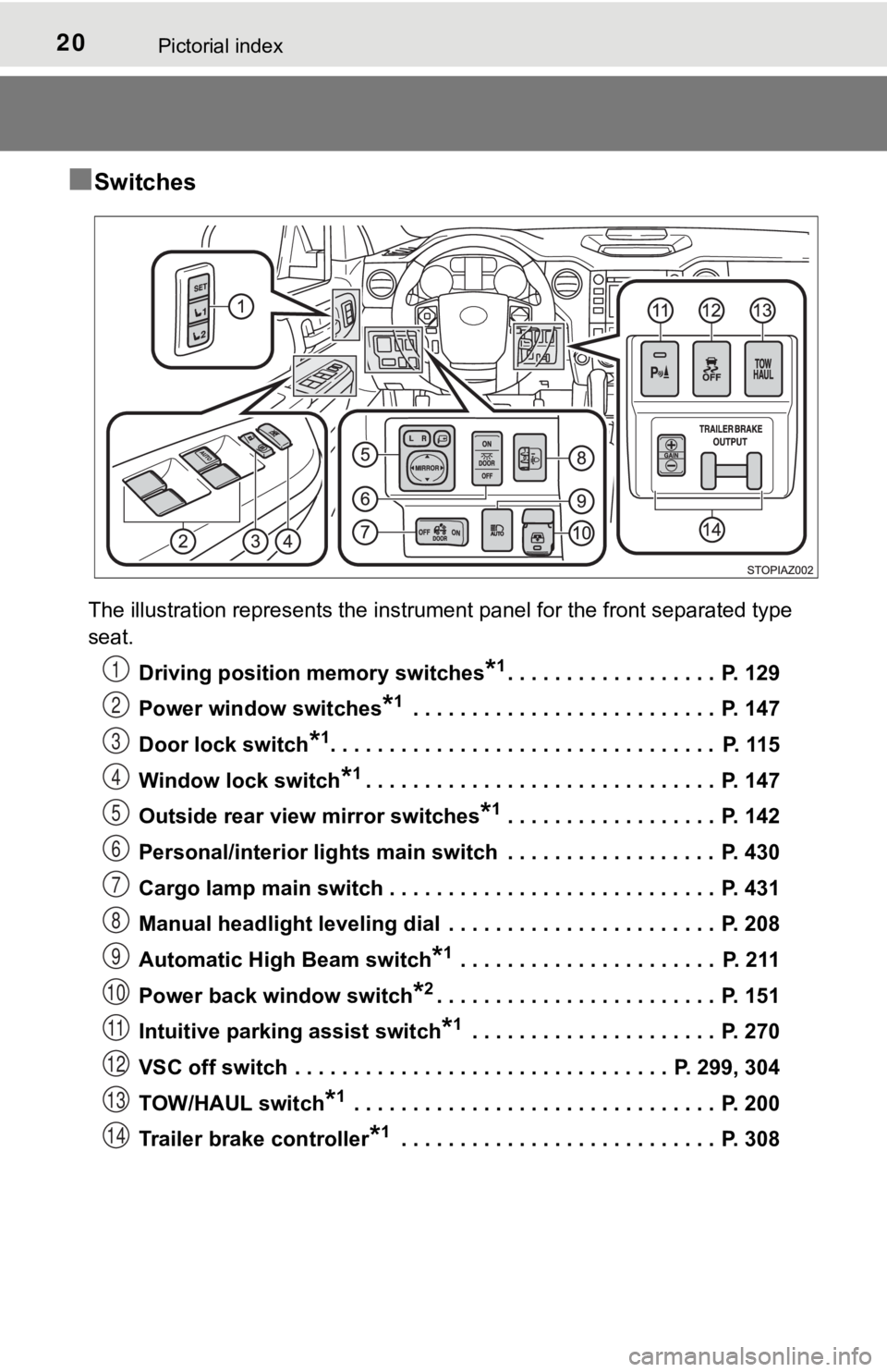
■Switches
The illustration represents the instrument panel for the front separated type
seat.Driving position memory switches
*1. . . . . . . . . . . . . . . . . . P. 129
Power window switches
*1 . . . . . . . . . . . . . . . . . . . . . . . . . . P. 147
Door lock switch
*1. . . . . . . . . . . . . . . . . . . . . . . . . . . . . . . . . P. 115
Window lock switch
*1. . . . . . . . . . . . . . . . . . . . . . . . . . . . . . P. 147
Outside rear view mirror switches
*1 . . . . . . . . . . . . . . . . . . P. 142
Personal/interior lights main switch . . . . . . . . . . . . . . . . . . P. 430
Cargo lamp main switch . . . . . . . . . . . . . . . . . . . . . . . . . . . . P. 431
Manual headlight leveling dial . . . . . . . . . . . . . . . . . . . . . . . P. 208
Automatic High Beam switch
*1 . . . . . . . . . . . . . . . . . . . . . . P. 211
Power back window switch
*2. . . . . . . . . . . . . . . . . . . . . . . . P. 151
Intuitive parking assist switch
*1 . . . . . . . . . . . . . . . . . . . . . P. 270
VSC off switch . . . . . . . . . . . . . . . . . . . . . . . . . . . . . . . . P. 299, 304
TOW/HAUL switch
*1 . . . . . . . . . . . . . . . . . . . . . . . . . . . . . . . P. 200
Trailer brake controller
*1 . . . . . . . . . . . . . . . . . . . . . . . . . . . P. 308
1
2
3
4
5
6
7
8
9
10
11
12
13
14
Page 93 of 672

932. Instrument cluster
2
Instrument cluster
*1: These lights turn on when the engine switch is turned to the “ON” positionto indicate that a system check is being performed. They will turn off after
the engine is started, or after a few seconds. There may be a m alfunction
in a system if the lights do not come on, or if the lights do n ot turn off. Have
the vehicle inspected by your Toyota dealer for details.
*2: The light flashes to indicate that the system is operating. Front fog light indicator
(
P. 216)
*1
“TRAC OFF” indicator
(P. 302)
*1, 5
“AIR BAG ON” and
“AIR BAG OFF”
indicators ( P. 50)
*9
“RCTA” indicator
(P. 286)
Security indicator
( P. 76, 85)
*6, 9
Radar cruise control
indicator ( P. 252)
*1“AUTO LSD” indicator
(P. 299, 302)
*1, 2Slip indicator
( P. 302)*1, 8, 9
PCS warning light
(P. 235)
*1VSC off indicator
(P. 299, 302)
(4WD models)
“4HI” indicator ( P. 296)
“TOW HAUL” indicator
( P. 200)
(4WD models)
“4LO” indicator ( P. 296)
*9“BSM” indicator
(P. 286)*6
(Green)
Trailer connection
indicator ( P. 308)
*3, 4, 9
BSM outside rear view
mirror indicator
(P. 286)
*6, 7
Low outside temperature
indicator
Page 137 of 672
1373-4. Adjusting the steering wheel and mirrors
3
Operation of each component
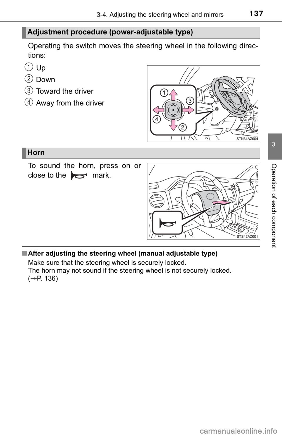
Operating the switch moves the steering wheel in the following direc-
tions:
Up
Down
Toward the driver
Away from the driver
To sound the horn, press on or
close to the mark.
■ After adjusting the steering wheel (manual adjustable type)
Make sure that the steering wheel is securely locked.
The horn may not sound if the steer ing wheel is not securely locked.
( P. 136)
Adjustment procedure (power-adjustable type)
1
2
3
4
Horn
Page 138 of 672
1383-4. Adjusting the steering wheel and mirrors
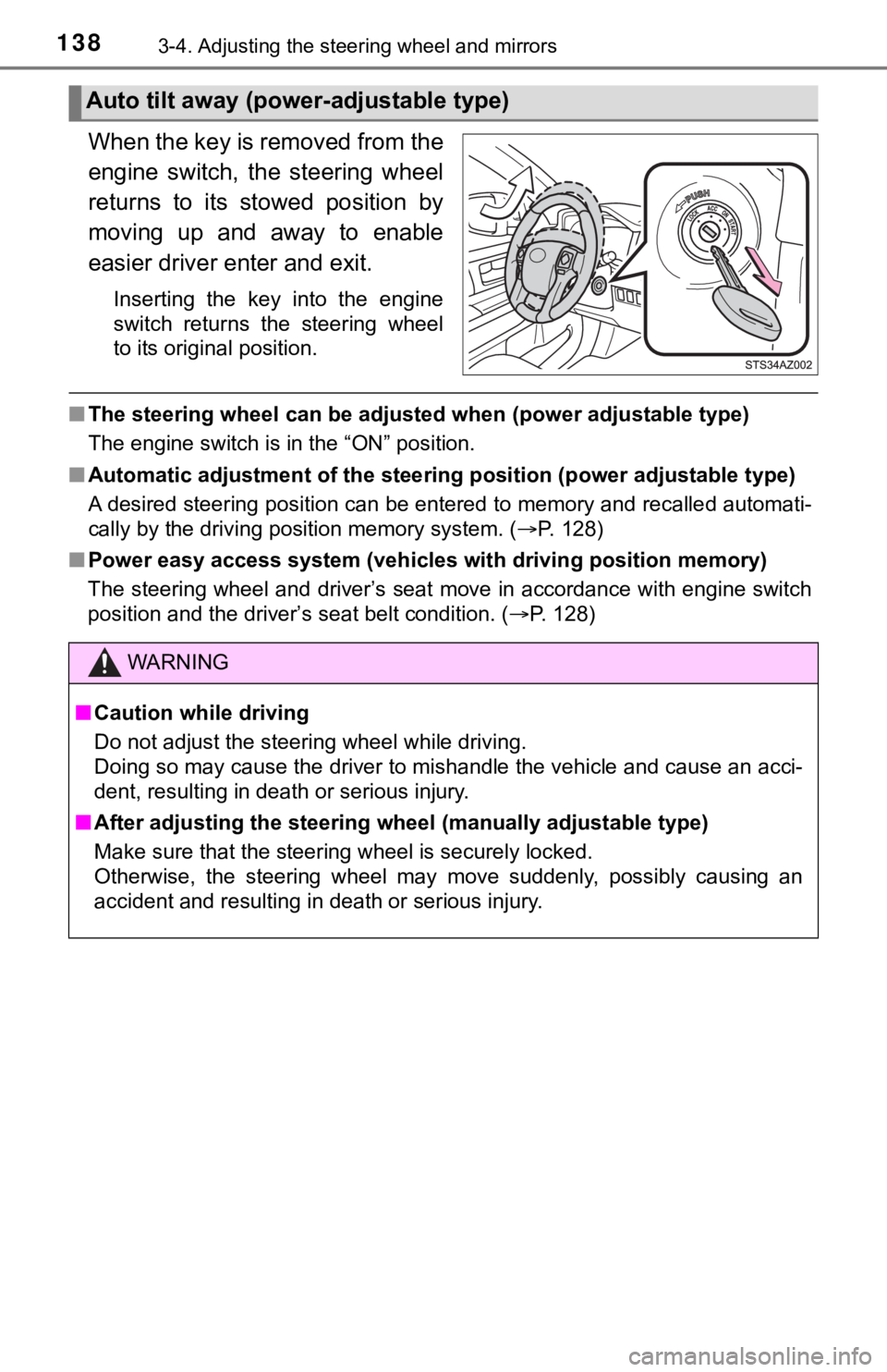
When the key is removed from the
engine switch, the steering wheel
returns to its stowed position by
moving up and away to enable
easier driver enter and exit.
Inserting the key into the engine
switch returns the steering wheel
to its original position.
■The steering wheel can be adjusted when (power adjustable type)
The engine switch is in the “ON” position.
■ Automatic adjustment of the stee ring position (power adjustable type)
A desired steering position can be entered to memory and recall ed automati-
cally by the driving position memory system. ( P. 128)
■ Power easy access system (vehicles with driving position memory )
The steering wheel and driver’s seat move in accordance with en gine switch
position and the driver’s seat belt condition. ( P. 128)
Auto tilt away (power-adjustable type)
WARNING
■Caution while driving
Do not adjust the steering wheel while driving.
Doing so may cause the driver to mishandle the vehicle and caus e an acci-
dent, resulting in death or serious injury.
■ After adjusting the steering wheel (manually adjustable type)
Make sure that the steering wheel is securely locked.
Otherwise, the steering wheel may move suddenly, possibly causi ng an
accident and resulting in death or serious injury.
Page 145 of 672
1453-4. Adjusting the steering wheel and mirrors
3
Operation of each component
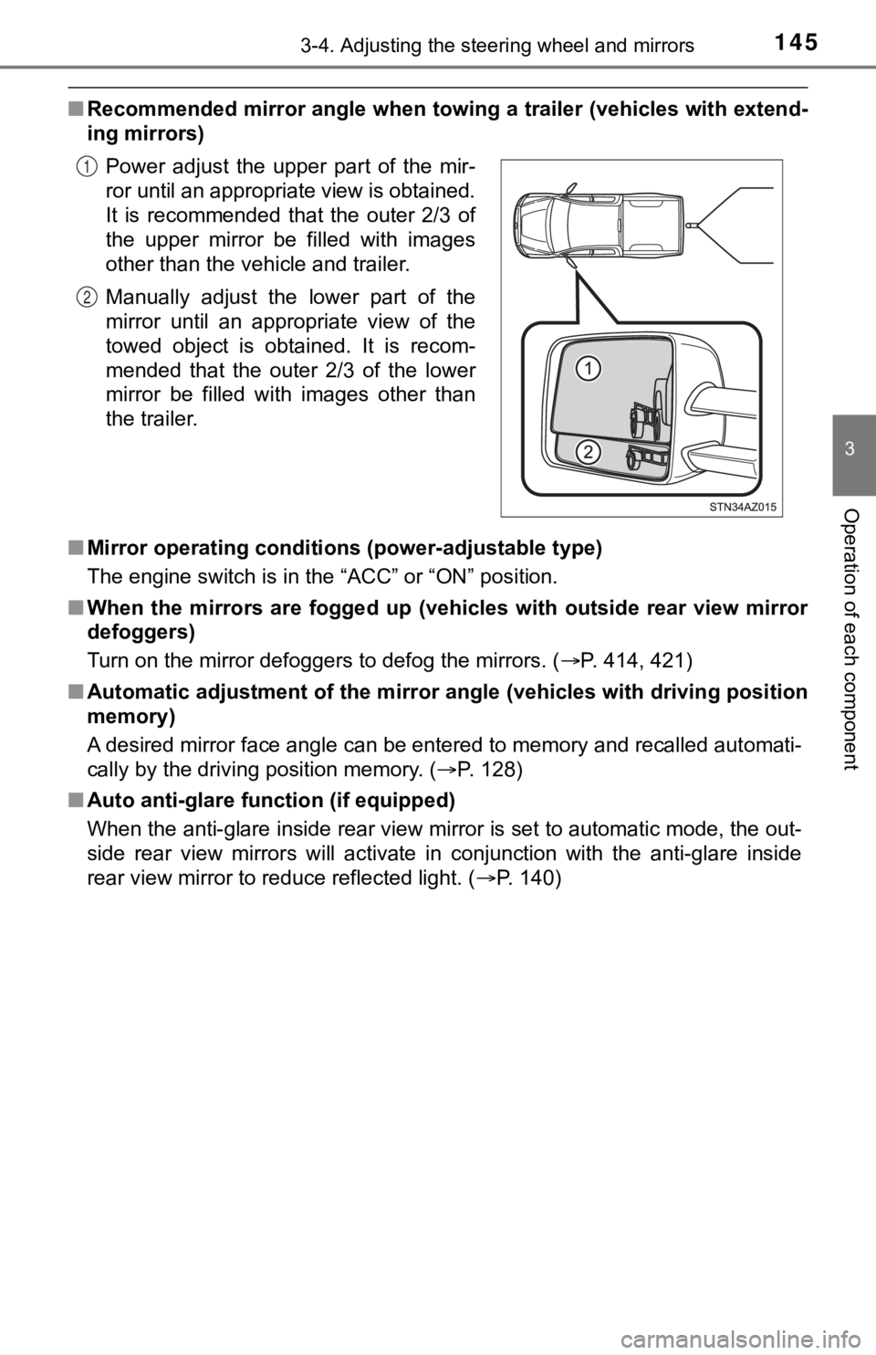
■Recommended mirror angle when to wing a trailer (vehicles with extend-
ing mirrors)
■ Mirror operating conditions (power-adjustable type)
The engine switch is in the “ACC” or “ON” position.
■ When the mirrors are fogged up ( vehicles with outside rear view mirror
defoggers)
Turn on the mirror defoggers to defog the mirrors. ( P. 414, 421)
■ Automatic adjustment of the mirr or angle (vehicles with driving position
memory)
A desired mirror face angle can be entered to memory and recall ed automati-
cally by the driving position memory. ( P. 128)
■ Auto anti-glare function (if equipped)
When the anti-glare inside rear view mirror is set to automatic mode, the out-
side rear view mirrors will activate in conjunction with the an ti-glare inside
rear view mirror to reduce reflected light. ( P. 140)
Power adjust the upper part of the mir-
ror until an appropriate view is obtained.
It is recommended that the outer 2/3 of
the upper mirror be filled with images
other than the vehicle and trailer.
Manually adjust the lower part of the
mirror until an appropriate view of the
towed object is obtained. It is recom-
mended that the outer 2/3 of the lower
mirror be filled with images other than
the trailer.
1
2
Page 190 of 672
1904-1. Before driving
■Trailer brake controller
P. 308
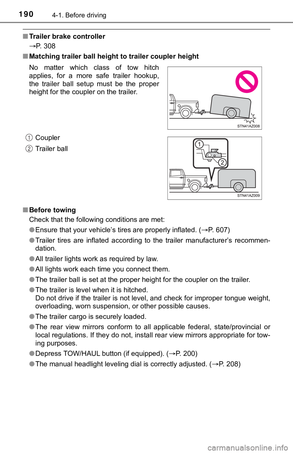
■ Matching trailer ball height to trailer coupler height
■ Before towing
Check that the following conditions are met:
●Ensure that your vehicle’s tires are properly inflated. ( P. 607)
● Trailer tires are inflated according to the trailer manufacture r’s recommen-
dation.
● All trailer lights work as required by law.
● All lights work each time you connect them.
● The trailer ball is set at the proper height for the coupler on the trailer.
● The trailer is level when it is hitched.
Do not drive if the trailer is not level, and check for imprope r tongue weight,
overloading, worn suspension, or other possible causes.
● The trailer cargo is securely loaded.
● The rear view mirrors conform to all applicable federal, state/provincial or
local regulations. If they do not, install rear view mirrors ap propriate for tow-
ing purposes.
● Depress TOW/HAUL button (if equipped). ( P. 200)
● The manual headlight leveling dial is correctly adjusted. ( P. 208)
No matter which class of tow hitch
applies, for a more safe trailer hookup,
the trailer ball setup must be the proper
height for the coupler on the trailer.
Coupler
Trailer ball
1
2
Page 214 of 672

2144-3. Operating the lights and wipers
●The high beam may be turned on or off when the driver does not expect it.
● Bicycles or similar objects may not be detected.
● In the situations shown below, the system may not be able to accurately
detect surrounding brightness levels. This may cause the low be ams to
remain on or the high beams to cause problems for pedestrians, vehicles
ahead or other parties. In these cases, manually switch between the high
and low beams.
• In bad weather (rain, snow, fog, sandstorms, etc.)
• The windshield is obscured by fog, mist, ice, dirt, etc.
• The windshield is cracked or damaged.
• The camera sensor is deformed or dirty.
• The camera sensor temperature is extremely high.
• Surrounding brightness levels are equal to those of headlights , tail lights
or fog lights.
• Vehicles ahead have headlights that are either switched off, d irty, are
changing color, or are not aimed properly.
• When driving through an area of intermittently changing brightness and
darkness.
• When frequently and repeatedly driving ascending/descending roads, or roads with rough, bumpy or uneven surfaces (such as stone-paved
roads, gravel tracks, etc.).
• When frequently and repeatedly taking curves or driving on a w inding
road.
• There is a highly reflective object ahead of the vehicle, such as a sign or a mirror.
• The back of a vehicle ahead is highly reflective, such as a co ntainer on a
truck.
• The vehicle’s headlights are damaged or dirty.
• The vehicle is listing or tilting, due to a flat tire, a trailer being towed etc.
• The high beam and low beam are repeatedly being switched betwe en in
an abnormal manner.
• The driver believes that the high beam may be causing problems or dis-
tress to other drivers or pedestrians nearby.
Page 286 of 672

2864-5. Using the driving support systems
BSM (Blind Spot Monitor)
The Blind Spot Monitor is a system that has 2 functions;
● The Blind Spot Monitor function
Assists the driver in making t he decision when changing lanes
● The Rear Cross Traffic Alert function
Assists the driver when backing up
These functions use same sensors.
Multi-information display
Turning the BSM function/RCTA function on/off. ( P. 287)
Outside rear view mirror indicators
Blind Spot Monitor function:
When a vehicle is detected in a blind spot of the outside rear view mir-
rors or approaching rapidly from behind into a blind spot, the outside
rear view mirror indicator on the detected side will illuminate. If the turn
signal lever is operated toward the detected side, the outside rear view
mirror indicator will flash.
Rear Cross Traffic Alert function:
When a vehicle approaching from the right or left at the rear of the vehi-
cle is detected, both outside rear view mirror indicators will flash.
: If equipped
Summary of the Blind Spot Monitor
1
2