Page 576 of 672
5768-2. Steps to take in an emergency
Vehicles with aluminum wheels: Remove the center wheel orna-
ment by pushing from the reverse side.
Lay down the tire with the valve
stem facing up and install the
holding bracket, inserting the
claw into the wheel lug nut hole.
Turn the jack handle extension
clockwise to take up slack in
the chain.
Then, check to ensure the claw is
in the wheel lug nut hole and the
holding bracket is centered in the
wheel hub.
Holding bracket
Claw
While raising, secure the tire, tak-
ing care that the tire goes straight
up without catching on any sur-
rounding part, to prevent it from
flying forward during a collision or
sudden braking.
Tightening torque:
34.7 ft·lbf (46.6 N·m, 4.8 kgf·m)
Stowing the flat tire, jack and all tools
1
incorrect
correct
O
1
2
Page 577 of 672

5778-2. Steps to take in an emergency
8
When trouble arises
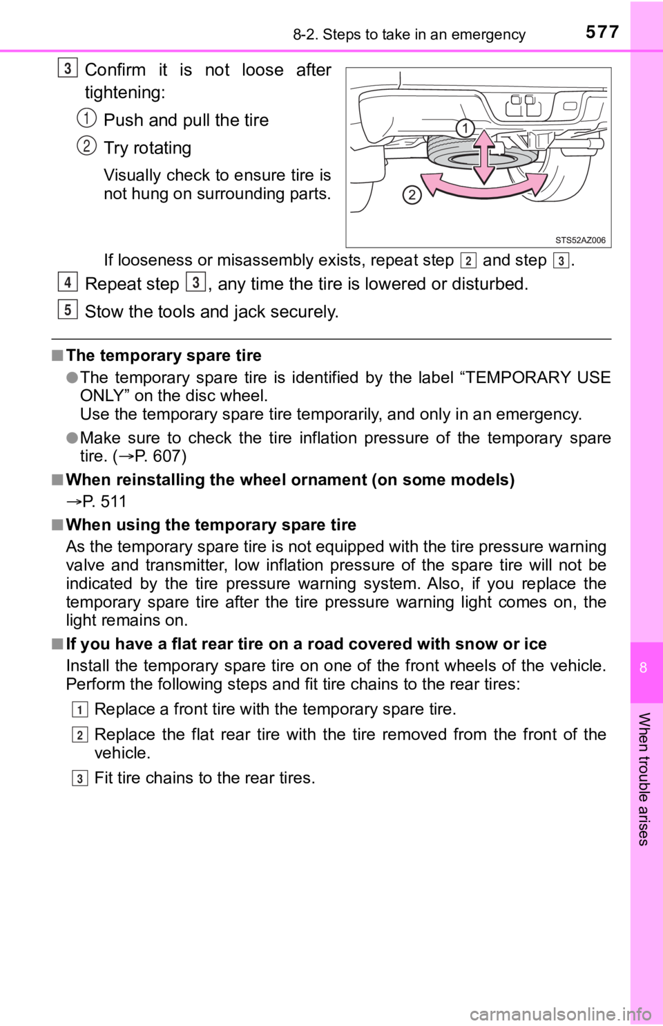
Confirm it is not loose after
tightening:Push and pull the tire
Try rotating
Visually check to ensure tire is
not hung on surrounding parts.
If looseness or misassembly ex ists, repeat step and step .
Repeat step , any time the tire is lowered or disturbed.
Stow the tools and jack securely.
■The temporary spare tire
●The temporary spare tire is identified by the label “TEMPORARY USE
ONLY” on the disc wheel.
Use the temporary spare tire temp orarily, and only in an emergency.
●Make sure to check the tire inflation pressure of the temporary spare
tire. ( P. 6 0 7 )
■When reinstalling the wheel ornament (on some models)
P. 5 1 1
■When using the temporary spare tire
As the temporary spare tire is no t equipped with the tire pressure warning
valve and transmitter, low inflation pressure of the spare tire will not be
indicated by the tire pressure warning system. Also, if you rep lace the
temporary spare tire after the tire pressure warning light come s on, the
light remains on.
■If you have a flat rear tire on a road covered with snow or ice
Install the temporary spare tire on one of the front wheels of the vehicle.
Perform the following steps and f it tire chains to the rear tires:
Replace a front tire with the temporary spare tire.
Replace the flat rear tire with the tire removed from the front of the
vehicle.
Fit tire chains to the rear tires.
3
1
2
23
43
5
1
2
3
Page 579 of 672

5798-2. Steps to take in an emergency
8
When trouble arises
NOTICE
■Do not drive the vehicle with a flat tire
Do not continue driving with a flat tire.
Driving even a short distance with a flat tire can damage the tire and the
wheel beyond repair.
■Driving with tire chains a nd the temporary spare tire
Do not fit tire chains to t he temporary spare tire.
Tire chains may damage the vehicle body and adversely affect dr iving
performance.
■When replacing the tires
When removing or fitting the wheels, tires or the tire pressure warning
valve and transmitter, contact your Toyota dealer as the tire p ressure
warning valve and transmitter may be damaged if not handled cor rectly.
■To avoid damage to the tire pressure warning valves and transmi t-
ters
When a tire is repaired with liqui d sealants, the tire pressure warning
valve and transmitter may not operate properly. If a liquid sea lant is
used, contact your Toyota dealer or other qualified service shop as soon
as possible. Make sure to replac e the tire pressure warning valve and
transmitter when replacing the tire. ( P. 4 9 6 )
Page 588 of 672

5888-2. Steps to take in an emergency
If the vehicle becomes stuck
Stop the engine. Set the parking brake and shift the shift lever to P.
Remove the mud, snow or sand from around the rear wheels.
Place wood, stones or some other material to help provide tract ion
under the rear wheels.
Restart the engine.
Shift the shift lever to D or R and release the parking brake. Then,
while exercising caution, de press the accelerator pedal.
■When it is difficult to free the vehicle
Press to turn off TRAC.
Turn off TRAC and/or VSC if these functions are hampering your attempts to
free the vehicle. ( P. 302, 304)
Carry out the following procedures if the tires spin or the vehicle
becomes stuck in mud, dirt or snow:
WARNING
■When attempting to f ree a stuck vehicle
If you choose to push the vehicle back and forth to free it, ma ke sure the
surrounding area is clear to avoid striking other vehicles, obj ects or people.
The vehicle may also lunge forward or lunge back suddenly as it becomes
free. Use extreme caution.
■ When shifting the shift lever
Be careful not to shift the shift lever with the accelerator pe dal depressed.
This may lead to unexpected rapid acceleration of the vehicle t hat may
cause an accident resulting in death or serious injury.
1
2
3
4
5
Page 589 of 672
5898-2. Steps to take in an emergency
8
When trouble arises
NOTICE
■To avoid damage to the trans mission and other components
● Avoid spinning the rear wheels and depressing the accelerator p edal more
than necessary.
● If the vehicle remains stuck even after these procedures are pe rformed,
the vehicle may require towing to be freed.
● When a warning message for the automatic transmission fluid tem perature
is displayed while attempting to free a stuck vehicle, immediat ely remove
your foot from the accelerator pedal and wait until the warning message
disappears. Otherwise, the transmission may become damaged.
( P. 555)
Page 592 of 672
5929-1. Specifications
Maintenance data (fuel, oil level, etc.)
2WD models
*1: Unladen vehicle
*2: P255/70R18 tires
*3: P275/65R18 tires
*4: P275/55R20 tires
Dimensions
Cab typeDouble Cab CrewMax
Bed typeStandardLongShort
Overall length228.9 in. (5815
mm) 247.8 in.
(6295 mm) 228.9 in.
(5815 mm)
Overall width 79.9 in. (2030 mm)
Overall
height
*1
75.9 in.
(1930 mm)
*275.7 in.
(1925 mm)
*2
75.7 in.
(1925 mm)
*3,*475.5 in.
(1920 mm)
*3,*4
Wheelbase 145.6 in. (3700
mm) 164.5 in.
(4180 mm) 145.6 in.
(3700 mm)
Front tread 67.9 in. (1725 mm)
Rear tread67.9 in. (1725 mm)
Page 593 of 672
5939-1. Specifications
9
Vehicle specifications
4WD models
*1: Unladen vehicle
*2: P255/70R18 tires
*3: P275/65R18 tires
*4: P275/55R20 tires
Cab typeDouble Cab CrewMax
Bed typeStandardLongShort
Overall length228.9 in. (5815
mm) 247.8 in.
(6295 mm) 228.9 in.
(5815 mm)
Overall width 79.9 in. (2030 mm)
Overall
height
*1
76.3 in.
(1940 mm)
*276.1 in.
(1935 mm)
*2
76.1 in.
(1935 mm)
*3,*475.9 in.
(1930 mm)
*3,*4
Wheelbase 145.6 in. (3700
mm) 164.5 in.
(4180 mm) 145.6 in.
(3700 mm)
Front tread 67.9 in. (1725 mm)
Rear tread67.9 in. (1725 mm)
Page 607 of 672

6079-1. Specifications
9
Vehicle specifications
*1: Minimum pedal clearance when depressed with a force of 110 lbf (490 N,
50 kgf) with the engine running.
*2: Parking brake pedal travel when depressed with a force of 67.1 lbf (300 N, 30.6 kgf).
Ty p e A
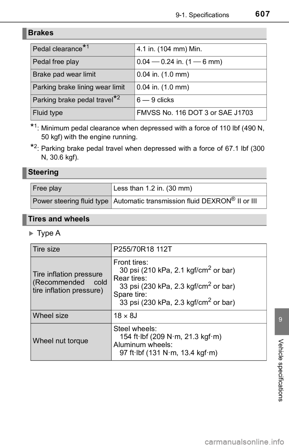
Brakes
Pedal clearance*14.1 in. (104 mm) Min.
Pedal free play 0.04 0.24 in. (1 6 mm)
Brake pad wear limit 0.04 in. (1.0 mm)
Parking brake lining wear limit 0.04 in. (1.0 mm)
Parking brake pedal travel*26 — 9 clicks
Fluid typeFMVSS No. 116 DOT 3 or SAE J1703
Steering
Free playLess than 1.2 in. (30 mm)
Power steering fluid typeAutomatic transmission fluid DEXRON® II or III
Tires and wheels
Tire sizeP255/70R18 112T
Tire inflation pressure
(Recommended cold
tire inflation pressure)
Front tires:
30 psi (210 kPa, 2.1 kgf/cm2 or bar)
Rear tires: 33 psi (230 kPa, 2.3 kgf/cm
2 or bar)
Spare tire: 33 psi (230 kPa, 2.3 kgf/cm
2 or bar)
Wheel size18 8J
Wheel nut torque
Steel wheels:
154 ft·lbf (209 N·m, 21.3 kgf·m)
Aluminum wheels: 97 ft·lbf (131 N·m, 13.4 kgf·m)