2018 SUBARU CROSSTREK fuse
[x] Cancel search: fusePage 19 of 474

(18,1)
北米Model "A1320BE-C" EDITED: 2017/ 10/ 10
&Instrument panel
1) Steering responsive fog lights OFF
switch (page 3-74)/Steering Responsive
Headlight off switch (page 3-72)
2) Illumination brightness control
(page 3-12)
3) Combination meter (page 3-8)
4) Type A multi-function display (black and
white) (page 3-42)/Type B multi-function
display (color LCD) (page 3-47)
5) Audio*
6) Hazard warning flasher switch (page 3-8)
7) Climate control (page 4-2)
8) Tilt/Telescopic steering (page 3-90)
9) BSD/RCTA OFF switch (page 7-52)
10) Fuse box (page 11-34)
11) Hood lock release knob (page 11-5)
12) Vehicle Dynamics Control OFF switch
(page 7-37)*: For details about how to use the audio
and navigation system (if equipped), refer
to the separate navigation/audio Owner’s
Manual.NOTEFor models with the EyeSight system:
Refer to the Owner’s Manual supple-
ment for the EyeSight system.
16
Page 143 of 474

(148,1)
北米Model "A1320BE-C" EDITED: 2017/ 10/ 10
NOTE.If the connection between the com-
bination meter and battery is broken for
any reason such as vehicle mainte-
nance or fuse replacement, the data
recorded on the trip meter will be lost.
.If you press the TRIP RESET switch
when the ignition switch is in the
“LOCK”/“OFF”or“ACC”position, the
odometer/trip meter will light up. It is
possible to switch between the A trip
meter and B trip meter indications while
the odometer/trip meter is lit up.
In addition, it is possible to reset the trip
meter by pressing and holding the TRIP
RESET switch.
The indicators will turn off when:
–The TRIP RESET switch is not
operated for approximately 10 sec-
onds.
–The driver’s door is opened and
then closed.
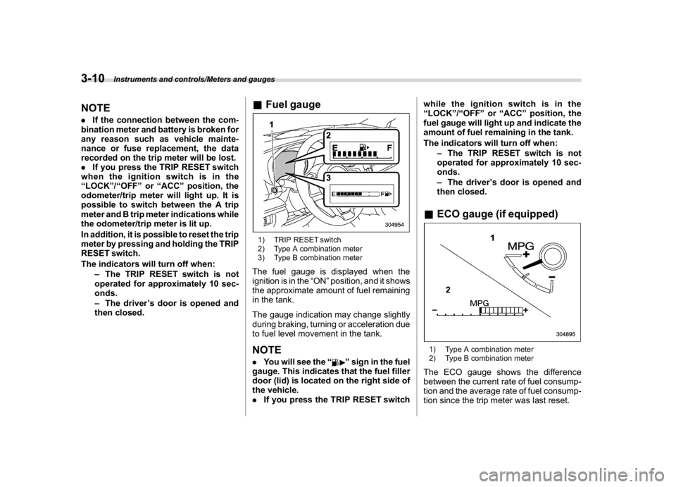
&Fuel gauge1) TRIP RESET switch
2) Type A combination meter
3) Type B combination meterThe fuel gauge is displayed when the
ignition is in the“ON”position, and it shows
the approximate amount of fuel remaining
in the tank.
The gauge indication may change slightly
during braking, turning or acceleration due
to fuel level movement in the tank.NOTE.You will see the“
”sign in the fuel
gauge. This indicates that the fuel filler
door (lid) is located on the right side of
the vehicle.
.If you press the TRIP RESET switchwhile the ignition switch is in the
“LOCK”/“OFF”or“ACC”position, the
fuel gauge will light up and indicate the
amount of fuel remaining in the tank.
The indicators will turn off when:
–The TRIP RESET switch is not
operated for approximately 10 sec-
onds.
–The driver’s door is opened and
then closed.
&ECO gauge (if equipped)1) Type A combination meter
2) Type B combination meterThe ECO gauge shows the difference
between the current rate of fuel consump-
tion and the average rate of fuel consump-
tion since the trip meter was last reset.
Instruments and controls/Meters and gauges
3-10
Page 179 of 474

(184,1)
北米Model "A1320BE-C" EDITED: 2017/ 10/ 10
time a complete hour has elapsed. If the
display is giving a reading other than the
journey time, the display switches to the
journey time, flashes for 5 seconds, and
returns to its original reading each time a
complete hour has elapsed.NOTEThe journey time is reset when the
ignition switch is turned to the“ACC”
or“LOCK”/“OFF”position.
!Average vehicle speed1) When units in miles is selected
2) When units in km is selectedThis display shows the average vehicle
speed since the trip meter was last reset.
Pressing the TRIP RESET switch toggles
the display between the average vehiclespeed corresponding to the A trip meter
display and the average vehicle speed
corresponding to the B trip meter display.
When either of the trip meter displays is
reset, the corresponding average vehicle
speed value is also reset.
NOTEWhen either trip meter display is reset,
the average vehicle speed correspond-
ing to that trip meter display is not
shown until the vehicle has subse-
quently covered a distance of 1 mile
(or 1 km).
!Turn off display of driving informa-
tion display
Select the blank space in the menu to exit
the driving information display selection.NOTE.The average fuel consumption and
average vehicle speed are calculated
even while the driving information dis-
play is not displayed.
.Even if you turn off the driving
information display, the display will
automatically turn on when the battery
voltage is disconnected and then re-
connected for battery replacement or
fuse replacement.
&Outside temperature indica-
tor1) U.S.-spec. models
2) Except U.S.-spec. modelsNOTE.The outside temperature indicator
shows the temperature around the
sensor. Therefore, the temperature in-
dication may differ from the actual
outside air temperature.
.The temperature unit cannot be
changed.
Instruments and controls/Multi-function display (black and white)
3-46
Page 186 of 474

(191,1)
北米Model "A1320BE-C" EDITED: 2017/ 10/ 10
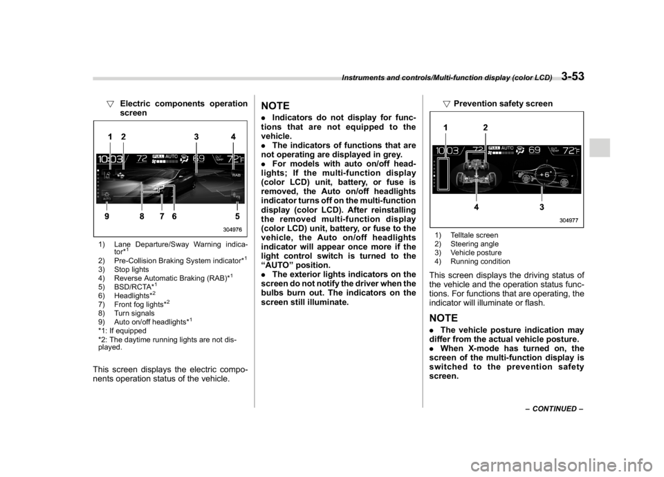
!Electric components operation
screen1) Lane Departure/Sway Warning indica-
tor*
1
2) Pre-Collision Braking System indicator*
1
3) Stop lights
4) Reverse Automatic Braking (RAB)*
1
5) BSD/RCTA*
1
6) Headlights*
2
7) Front fog lights*
2
8) Turn signals
9) Auto on/off headlights*
1
*1: If equipped
*2: The daytime running lights are not dis-
played.This screen displays the electric compo-
nents operation status of the vehicle.
NOTE.Indicators do not display for func-
tions that are not equipped to the
vehicle.
.The indicators of functions that are
not operating are displayed in grey.
.For models with auto on/off head-
lights; If the multi-function display
(color LCD) unit, battery, or fuse is
removed, the Auto on/off headlights
indicator turns off on the multi-function
display (color LCD). After reinstalling
the removed multi-function display
(color LCD) unit, battery, or fuse to the
vehicle, the Auto on/off headlights
indicator will appear once more if the
light control switch is turned to the
“AUTO”position.
.The exterior lights indicators on the
screen do not notify the driver when the
bulbs burn out. The indicators on the
screen still illuminate.!Prevention safety screen
1) Telltale screen
2) Steering angle
3) Vehicle posture
4) Running conditionThis screen displays the driving status of
the vehicle and the operation status func-
tions. For functions that are operating, the
indicator will illuminate or flash.NOTE.The vehicle posture indication may
differ from the actual vehicle posture.
.When X-mode has turned on, the
screen of the multi-function display is
switched to the prevention safety
screen.
–CONTINUED–
Instruments and controls/Multi-function display (color LCD)
3-53
3
Page 268 of 474

(277,1)
北米Model "A1320BE-C" EDITED: 2017/ 10/ 10
(4) If the engine still refuses to start,
contact your nearest SUBARU dealer
for assistance.
6. Confirm that all warning and indicator
lights have turned off after the engine has
started. The fuel injection system auto-
matically lowers the idle speed as the
engine warms up.
While the engine is warming up, make sure
that the select lever is at the“P”or“N”
position and that the parking brake is
applied.
CAUTION
If you restart the engine while the
vehicle is moving, shift the select
lever into the“N”position. Do not
attempt to place the select lever of a
moving vehicle into the“P”position.
&Stopping the engineThe ignition switch should be turned off
only when the vehicle is stopped and the
engine is idling.
WARNING
Do not stop the engine when the
vehicle is moving. This will cause
loss of power to the power steering
and the brake booster, making steer-
ing and braking more difficult. It
could also result in accidental acti-
vation of the“LOCK”/“OFF”posi-
tion on the ignition switch, causing
the steering wheel to lock.
Starting and stopping engine
(models with push-button
start system)&Safety precautionsRefer to“Safety precautions”F2-3.&Operating range for push-
button start systemRefer to“Operating range for push-button
start system”F3-6.&Starting engine
WARNING
.There are some general precau-
tions when starting the engine.
Carefully read the precautions
described in“Starting engine”
F7-9.
.If the indicator on the push-but-
ton ignition switch flashes in
green after the engine has
started, never drive the vehicle.
The steering is still locked, and it
may result in an accident.
–CONTINUED–
Starting and operating/Starting and stopping engine (models with push-button start system)
7-11
7
Page 383 of 474

(396,1)
北米Model "A1320BE-C" EDITED: 2017/ 10/ 10
Rotational direction of tires................................. 11-25
Tire rotation........................................................ 11-25
Tire replacement................................................. 11-26
Wheel replacement............................................. 11-27
Alloy wheels........................................................ 11-27
Windshield washer fluid..................................... 11-28
Adding the windshield washer fluid..................... 11-28
Windshield washer fluid...................................... 11-28
Replacement of wiper blades............................ 11-29
Windshield wiper blade assembly........................ 11-29
Window wiper blade rubber................................. 11-30
Rear window wiper blade assembly..................... 11-31
Rear window wiper blade rubber......................... 11-32
Battery................................................................. 11-33
Fuses................................................................... 11-34
Installation of accessories................................. 11-35Replacing bulbs...................................................11-36
Headlights (models with LED headlights)............ 11-36
Headlights (models with halogen headlights) ...... 11-36
Front turn signal light......................................... 11-38
Parking light....................................................... 11-38
Front fog light (if equipped)................................ 11-38
Rear combination lights...................................... 11-38
Backup light....................................................... 11-40
License plate light.............................................. 11-40
Map light............................................................ 11-41
Vanity mirror light (if equipped)........................... 11-41
Dome light and cargo area light.......................... 11-41
Other bulbs........................................................ 11-42
Replacing key battery.........................................11-42
Safety precautions.............................................. 11-42
Replacing battery of access key fob................... 11-43
Replacing transmitter battery.............................. 11-44
Maintenance and service
Page 388 of 474

(401,1)
北米Model "A1320BE-C" EDITED: 2017/ 10/ 10
Engine compartment overview
1) Brake fluid reservoir/Clutch fluid reservoir
(MT models) (page 11-15)
2) Fuse box (page 11-34)
3) Battery (page 11-33)
4) Windshield washer tank (page 11-28)
5) Radiator cap (page 11-11)
6) Engine oil filler cap (page 11-8)
7) Engine coolant reservoir (page 11-11)
8) Engine oil filter (page 11-9)
9) Engine oil level gauge (page 11-8)
10) Air cleaner case (page 11-12)
Maintenance and service/Engine compartment overview
11-7
11
Page 392 of 474

(405,1)
北米Model "A1320BE-C" EDITED: 2017/ 10/ 10
type, the maintenance interval is
shortened to that of the mixing
coolant.
.Do not splash the engine coolant
over painted parts. The alcohol
contained in the engine coolant
may damage the paint surface.
&Cooling fan, hose and con-
nectionsYour vehicle employs an electric cooling
fan which is thermostatically controlled to
operate when the engine coolant reaches
a specific temperature.
If the radiator cooling fan does not operate
even when the coolant temperature high
warning light blinks or illuminates inRED,
the cooling fan circuit may be defective.
Refer to“Coolant temperature low indica-
tor light/Coolant temperature high warning
light”F3-16.
Check the fuse and replace it if necessary.
Refer to“Fuses”F11-34 and“Fuse panel
located in the engine compartment”F12-
12.
If the fuse is not blown, have the cooling
system checked by your SUBARU dealer.
If frequent addition of coolant is necessary,
there may be a leak in the engine coolingsystem. It is recommended that the cooling
system and connections be checked for
leaks, damage, or looseness.
&Engine coolant!Checking the coolant level
WARNING
Never attempt to remove the radiator
cap until the engine has been shut
off and has cooled down completely.
Since the coolant is under pressure,
you may suffer serious burns from a
spray of boiling hot coolant when
the cap is removed.
1)“FULL”level mark
2)“LOW”level markCheck the coolant level at each fuel stop.
1. Check the coolant level on the outside
of the reservoir while the engine is cool.
2. If the level is close to or lower than the
“LOW”level mark, add coolant up to the
“FULL”level mark. If the reserve tank is
empty, remove the radiator cap and refill
coolant up to just below the filler neck as
shown in the following illustration.
–CONTINUED–
Maintenance and service/Cooling system
11-11
11