2018 RENAULT SCENIC symbol
[x] Cancel search: symbolPage 3 of 364

0.1
Translated from English. Copying or translation, in part or in full, is f\
orbidden unless prior written permission has been obtained from the vehicle manu-
facturer.
Welcome to your new vehicle
The descriptions of the models given in this handbook are based on the t\
echnical specifications at the time of writing. This hand-
book covers all items of equipment (both standard and optional) available for these models but whether or not these are
fitted to the vehicle depends on the version, options selected and the c\
ountry where the vehicle is sold.
This handbook may also contain information about items of equipment to b\
e introduced later in the model year.
Throughout the manual, the “approved Dealer” is your RENAULT Dealer.
Enjoy driving your new vehicle. This driver’s handbook contains the information necessary:
– for you to familiarise yourself with your vehicle, to use it to its best\
advantage and to benefit fully from the all the func tions and
the technical developments it incorporates.
– to ensure that it always gives the best performance by following the sim\
ple, but comprehensive advice concerning regular main -
tenance.
– to enable you to deal quickly with minor faults not requiring specialist\
attention.
It is well worth taking a few minutes to read this handbook to familiari\
se yourself with the information and guidelines it cont ains
about the vehicle and its functions and new features. If certain points \
are still unclear, our Network technicians will be only too
pleased to provide you with any additional information.
To help you, you will find the following symbols:
and These appear in the vehicle and indicate that you should consult the man\
ual for detailed information and/or
limits on operations with respect to your vehicle’s equipment.
anywhere in the manual indicates a hazard, danger or a safety recommenda\
tion.
Page 50 of 364

1.44
CHILD SAFETY: choosing a child seat mounting (3/3)
2
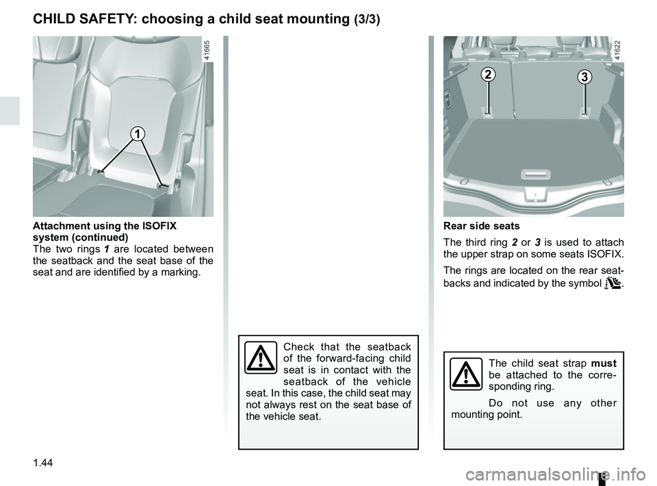
Rear side seats
The third ring 2 or 3 is used to attach
the upper strap on some seats ISOFIX.
The rings are located on the rear seat-
backs and indicated by the symbol
.
Attachment using the ISOFIX
system (continued)
The two rings
1 are located between
the seatback and the seat base of the
seat and are identified by a marking.
The child seat strap must
be attached to the corre-
sponding ring.
Do not use any other
mounting point.
1
3
Check that the seatback
of the forward-facing child
seat is in contact with the
seatback of the vehicle
seat. In this case, the child seat may
not always rest on the seat base of
the vehicle seat.
Page 101 of 364

1.95
EXTERIOR LIGHTING AND SIGNALS (1/6)
áMain beam headlights
With the dipped beam
headlights lit, push stalk 1. This indica-
tor light on the instrument panel comes
on.
To return to the dipped headlight posi-
tion, pull the stalk 1 towards you again.šSide lights
Turn ring 3 until the symbol is
opposite mark 2. This indicator light on
the instrument panel comes on.
kDipped beam
headlights
Manual operation
Turn ring 3 until the symbol is opposite
mark 2 . This indicator light on the in-
strument panel comes on.
Automatic operation
Turn ring 3 until the AUTO symbol is op-
posite mark 2: with the engine running,
the dipped beam headlights switch on
or off automatically depending on the
brightness of the light outside, without
any action on stalk 1.
Before driving at night:
check that the electrical
equipment is operating cor-
rectly. As a general precau-
tion, check that the lights are not
obscured (by dirt, mud, snow or ob-
jects being transported).
1
3
2
1
Page 103 of 364

1.97
3
2
1
Vehicles without a navigation
system
– With the vehicle stationary, press and hold the OK switch 5 to access
the settings menu;
– repeatedly press the control 6 up
or down until you reach the “Driving
assistance” menu. Press the OK
switch 5;
56
– repeatedly press control 6 up or down
until you reach the “Automaticmain
beam lights” menu, then press the
OK switch 5;
– press the OK switch 5 again to acti- vate or deactivate the function.
Activation/deactivation
To activate automatic main beam
headlights:
– turn ring 3 until the AUTO symbol is
opposite mark 2;
– push stalk 1.
Warning light
comes on the in-
strument panel.To deactivate automatic main beam
headlights:
– pull stalk 1 towards you;
– or turn ring 3 to a position other than AUTO.
Warning light
goes out on the in-
strument panel.
Note: make sure the windscreen is not
obscured (dirt, mud, snow, condensa-
tion etc.).
EXTERIOR LIGHTING AND SIGNALS (3/6)
Each time you start the engine, pull
and then push the stalk 1 to reacti-
vate the system.
Page 106 of 364

1.100
EXTERIOR LIGHTING AND SIGNALS (6/6)
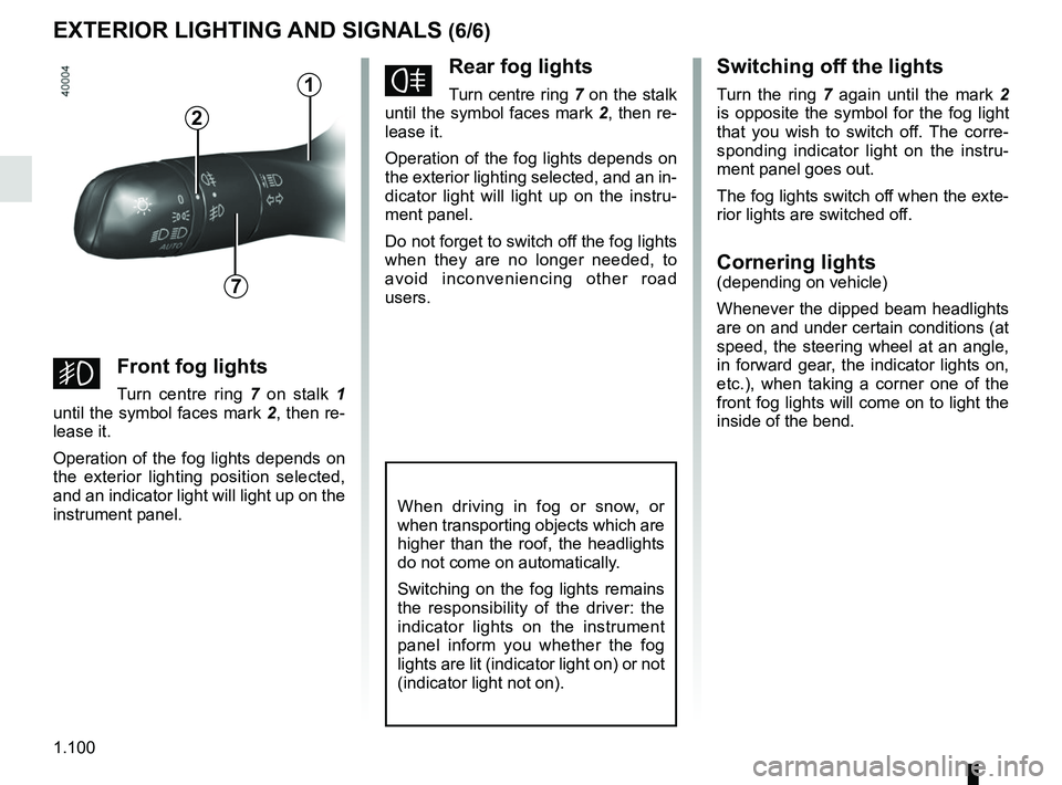
fRear fog lights
Turn centre ring 7 on the stalk
until the symbol faces mark 2, then re-
lease it.
Operation of the fog lights depends on
the exterior lighting selected, and an in-
dicator light will light up on the instru-
ment panel.
Do not forget to switch off the fog lights
when they are no longer needed, to
avoid inconveniencing other road
users.
Switching off the lights
Turn the ring 7 again until the mark 2
is opposite the symbol for the fog light
that you wish to switch off. The corre-
sponding indicator light on the instru-
ment panel goes out.
The fog lights switch off when the exte-
rior lights are switched off.
Cornering lights(depending on vehicle)
Whenever the dipped beam headlights
are on and under certain conditions (at
speed, the steering wheel at an angle,
in forward gear, the indicator lights on,
etc.), when taking a corner one of the
front fog lights will come on to light the
inside of the bend.
When driving in fog or snow, or
when transporting objects which are
higher than the roof, the headlights
do not come on automatically.
Switching on the fog lights remains
the responsibility of the driver: the
indicator lights on the instrument
panel inform you whether the fog
lights are lit (indicator light on) or not
(indicator light not on).
7
2
gFront fog lights
Turn centre ring 7 on stalk 1
until the symbol faces mark 2, then re-
lease it.
Operation of the fog lights depends on
the exterior lighting position selected,
and an indicator light will light up on the
instrument panel.
1
Page 115 of 364

1.109
REAR SCREEN WASH, WIPE (1/2)
1
3
YRear screen wiper
With the ignition on, turn ring 3
on stalk 1 to align the symbol with
mark 2.
– stop;
– intermittent wiping. The wipers will pause for several
seconds between sweeps. Wiping
frequency varies with vehicle
speed;
– slow continuous wiping. To stop operation, twist the ring 3 again
to the off position.
NB: when washing using a roller type
car wash, return the ring 3
on the
stalk 1 to the stop position to deactivate
automatic wiping.
Follow usage recommendations.
Before any action involving
the rear screen (washing
the vehicle, de-icing, clean-
ing, etc.) return stalk 1 to
the stop position.
Risk of injury and/or damage.
2
Efficiency of a wiper blade
Check the condition of the wiper
blades. How long they last depends
on you:
– it must remain clean: clean the blade and the screen regularly
with soapy water;
– do not use it when the screen is dry;
– free it from the screen when it has not been used for a long time.
In any event, replace them as soon
as they begin to lose efficiency: ap-
proximately every year (refer to the
information on “Wiper blades: re-
placement” in section 5).
Precautions for using the
wipers
– In freezing or snowy weather, clear the screen before starting
the wipers (risk of motor over-
heating);
– ensure that no objects are ob- structing the travel of the blade.
Do not use the wiper arm to open or
close the tailgate.
Page 136 of 364

2.16
The “Hybrid Assist” system uses an
electric motor to improve performance
of the combustion engine (acceleration,
starting on a slope etc.). The vehicle
has more acceleration torque available
while consuming less fuel.
BatteriesYour electric vehicle has two types of
battery:
– a 48 V traction battery;
– secondary 12 V battery.
“48 volt” traction battery
Located under the rear floor, this bat-
tery stores the energy recovered during
phases of deceleration. This energy is
used by the hybrid system to provide
additional torque to the combustion
engine.
“HYBRID ASSIST" SYSTEM: introduction (3/5)
Secondary 12V battery
The 12 V battery supplies the energy
required to operate vehicle equipment
(lights, windscreen wipers, ABS etc).
Please see the information under
“12 volt battery” in Section 4.
“48 volt” electrical circuit
The 48 V electrical circuit is denoted
by orange cables and parts bearing the
symbol
ṑ.
All interventions or modi-
fications to the vehicle’s
48 volt electrical system
(components, cables, con-
nectors, traction battery) are strictly
prohibited due to the risks this may
present to your safety. Call an ap-
proved Dealer.
Risk of electric shock.
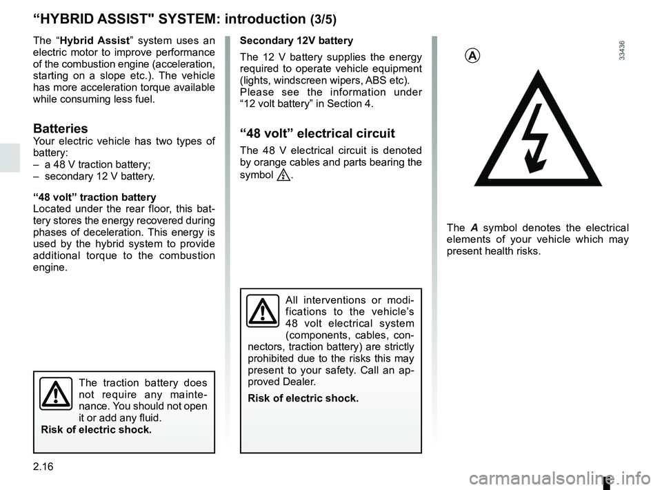
A
The A symbol denotes the electrical
elements of your vehicle which may
present health risks.
The traction battery does
not require any mainte-
nance. You should not open
it or add any fluid.
Risk of electric shock.
Page 320 of 364

5.28
FUSES (2/2)
Allocation of fuses
(the presence of certain fuses depends on the vehicle equipment level)\
Symbol Allocation SymbolAllocation
HWindscreen washer“Hybrid Assist” system
ëThird row accessories socket, boot accessories
socketÝTowbar socket
ÆFront cigarette lighter, front and rear second row
accessories socketDiagnostic socket, audio alarm
Not usedÌHorn
Heated door mirrorsInstrument panel, dashboard control lighting
×Brake lights, passenger compartment central unitRear electric windows
\bParking brakefFront windscreen wiper
Additional servoDDirection indicator lights, hazard warning lights
îRadio, multifunction screen, multimedia acces-
sories sockets, parking brake controlRear USB sockets on console
Passenger compartment centre unit, rear wiper,
rear fog light
OLocking the doors and luggage compartment