Page 261 of 348

4.9
LEVELS (2/3)
Brake fluid level
This should be checked frequently, and
any time you notice even the slightest
loss in braking efficiency.
The level should be read with the engine
switched off and on level ground.Level 2
It is normal for the level to drop as
the linings become worn, but it should
never drop below the “MINI” warning
line.
If you wish to check the disc and drum
wear yourself, you should obtain the
document explaining the checking pro-
cedure from our network or from the
manufacturer’s website. Topping up
After any operation on the hydraulic cir-
cuit, a specialist must replace the fluid.
Only use fluids approved by our
Technical Department (and taken from
a sealed container).
Replacement intervals
Refer to the Maintenance Document for
your vehicle.
Please note when work-
ing close to the engine that
it may be hot. The engine
cooling fan may also start
at any moment. The
warning
light in the engine compartment re-
minds you of this.
Risk of injury.
2
Before performing any
action in the engine com-
partment, the ignition must
be switched off (please see
the information on “Starting, stop-
ping the engine” in Section 2).
If there is an abnormal or repeated
drop in the fluid level, consult an ap-
proved dealer.
Page 263 of 348

4.11
BATTERY (1/2)
1
Battery 1 does not require any mainte-
nance. You should not open it or add
any fluid.
Handle the battery with care
as it contains sulphuric acid
which must not come into
contact with the eyes or
skin. If it does, wash the affected
area with plenty of cold water. If
necessary, consult a doctor.
Ensure that naked flames, red hot
objects and sparks do not come into
contact with the battery as there is a
risk of explosion.
Please note when work-
ing close to the engine that
it may be hot. In addition,
the engine cooling fan may
start at any moment. The
warning light in the engine compart-
ment reminds you of this.
Risk of injury.
Before performing any
action in the engine com-
partment, the ignition must
be switched off (please see
the information on “Starting, stop-
ping the engine” in Section 2).
Depending on the vehicle, a system
continuously checks the battery charge
status. If this decreases, the message
“Battery low start engine” is displayed
on the instrument panel. In this case,
start the engine. The message will go
off.
The charge status of your battery can
decrease especially if you use your ve-
hicle:
– for short journeys;
– for driving in town;
– when the temperature drops;
– after extended use of energy-con- suming devices (radio, etc.) with the
engine switched off.
Page 265 of 348

4.13
TYRE PRESSURE (1/2)
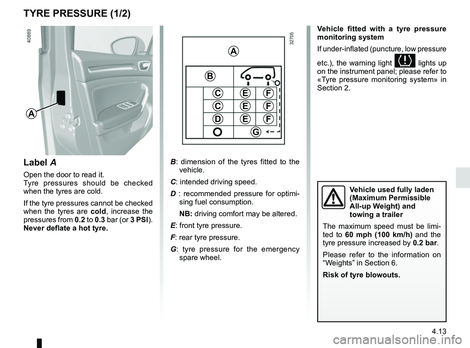
A
Label A
Open the door to read it.
Tyre pressures should be checked
when the tyres are cold.
If the tyre pressures cannot be checked
when the tyres are cold, increase the
pressures from 0.2 to 0.3 bar (or 3 PSI).
Never deflate a hot tyre. Vehicle fitted with a tyre pressure
monitoring system
If under-inflated (puncture, low pressure
etc.), the warning light
lights up
on the instrument panel; please refer to
«Tyre pressure monitoring system» in
Section 2.
A
C
D
FE
G
B
C
E
E
F
F
B : dimension of the tyres fitted to the
vehicle.
C: intended driving speed.
D : recommended pressure for optimi-
sing fuel consumption.
NB: driving comfort may be altered.
E: front tyre pressure.
F: rear tyre pressure.
G : tyre pressure for the emergency
spare wheel.
Vehicle used fully laden
(Maximum Permissible
All-up Weight) and
towing a trailer
The maximum speed must be limi-
ted to 60 mph (100 km/h) and the
tyre pressure increased by 0.2 bar.
Please refer to the information on
“Weights” in Section 6.
Risk of tyre blowouts.
Page 277 of 348

5.5
TYRE PRESSURE KIT (2/3)
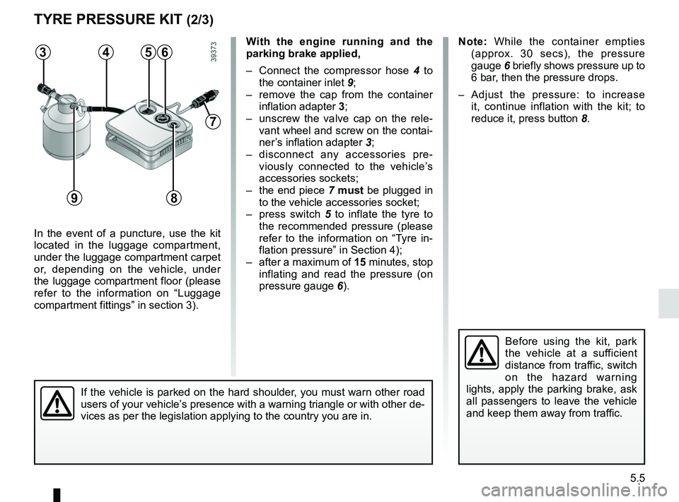
In the event of a puncture, use the kit
located in the luggage compartment,
under the luggage compartment carpet
or, depending on the vehicle, under
the luggage compartment floor (please
refer to the information on “Luggage
compartment fittings” in section 3).
Before using the kit, park
the vehicle at a sufficient
distance from traffic, switch
on the hazard warning
lights, apply the parking brake, ask
all passengers to leave the vehicle
and keep them away from traffic.
Note: While the container empties (approx. 30 secs), the pressure
gauge 6 briefly shows pressure up to
6 bar, then the pressure drops.
– Adjust the pressure: to increase it, continue inflation with the kit; to
reduce it, press button 8.
If the vehicle is parked on the hard shoulder, you must warn other road
users of your vehicle’s presence with a warning triangle or with other de-
vices as per the legislation applying to the country you are in.
With the engine running and the
parking brake applied,
– Connect the compressor hose 4 to
the container inlet 9;
– remove the cap from the container inflation adapter 3;
– unscrew the valve cap on the rele- vant wheel and screw on the contai-
ner’s inflation adapter 3;
– disconnect any accessories pre- viously connected to the vehicle’s
accessories sockets;
– the end piece 7 must be plugged in
to the vehicle accessories socket;
– press switch 5 to inflate the tyre to
the recommended pressure (please
refer to the information on “Tyre in-
flation pressure” in Section 4);
– after a maximum of 15 minutes, stop inflating and read the pressure (on
pressure gauge 6).563
9
7
4
8
Page 281 of 348

5.9
CHANGING A WHEEL (1/2)
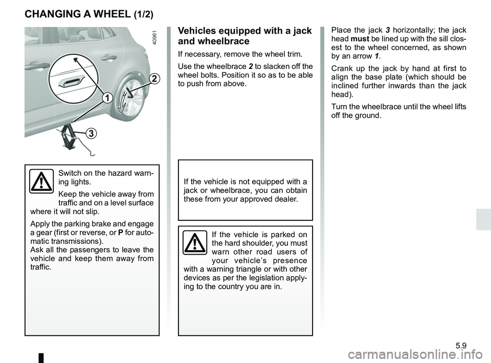
Place the jack 3 horizontally; the jack
head must be lined up with the sill clos-
est to the wheel concerned, as shown
by an arrow 1.
Crank up the jack by hand at first to
align the base plate (which should be
inclined further inwards than the jack
head).
Turn the wheelbrace until the wheel lifts
off the ground.
Switch on the hazard warn-
ing lights.
Keep the vehicle away from
traffic and on a level surface
where it will not slip.
Apply the parking brake and engage
a gear (first or reverse, or P for auto-
matic transmissions).
Ask all the passengers to leave the
vehicle and keep them away from
traffic.
If the vehicle is parked on
the hard shoulder, you must
warn other road users of
your vehicle’s presence
with a warning triangle or with other
devices as per the legislation apply-
ing to the country you are in.
If the vehicle is not equipped with a
jack or wheelbrace, you can obtain
these from your approved dealer.
Vehicles equipped with a jack
and wheelbrace
If necessary, remove the wheel trim.
Use the wheelbrace 2 to slacken off the
wheel bolts. Position it so as to be able
to push from above.
3
2
1
Page 284 of 348

5.12
TYRES (2/3)
Tyre pressures
Adhere to the tyre pressures (including
the emergency spare wheel). The tyre
pressures should be checked at least
once a month and additionally before
any long journey (refer to the label af-
fixed to the edge of the driver’s door).The pressures should be checked cold:
ignore higher pressures which may be
reached in hot weather or following a
high speed journey.
If the tyre pressures cannot be checked
when the tyres are
cold, increase the
pressures from 0.2 to 0.3 bar (or 3 PSI).
Never deflate a hot tyre.
Special note
Depending on the vehicle, there may
be an adapter which needs to be posi-
tioned on the valve before air is added. Vehicle fitted with a tyre pressure
monitoring system
If under-inflated (puncture, low pressure
etc.), the warning light
lights up
on the instrument panel; please refer to
“Tyre pressure monitoring system” in
Section 2.
Emergency spare wheel
Refer to the information on “Puncture”
and “Changing a wheel” in Section 5.
Changing wheels around
This practice is not recommended.
Incorrect tyre pressures
lead to abnormal tyre wear
and unusually hot running.
These are factors which
may seriously affect safety and lead
to:
– poor road holding,
– risk of bursting or tread separa- tion.
The pressure depends on the load
and the speed of use. Adjust the
pressure according to the condi-
tions of use (refer to the label affixed
to the edge of the driver’s door).
Please be aware that a
poorly tightened or miss-
ing valve cap can make the
tyres less airtight and lead
to pressure loss.
Always use valve caps identical to
those fitted originally and tighten
them fully.
Page 286 of 348

5.14
Any operation on (or modi-
fication to) the electrical
system must be performed
by an approved dealer
since an incorrect connection might
damage the electrical equipment
(harness, components and in partic-
ular the alternator). In addition, your
Dealer has all the parts required for
fitting these units.
LED dipped beam
headlights 1
Please see an authorised dealer.
LED main beam headlights 2
Please see an authorised dealer.
FRONT HEADLIGHTS: replacing the bulbs (1/2)
Halogen dipped beam
headlight
To change the bulb:
– open the bonnet;
– remove cover B;
– Turn the bulb holder a quarter turn 4;
– remove the bulb.
Bulb type: H7.
Once the bulb has been replaced,
check that it is properly secured.
BA
The bulbs are under pres-
sure and can break when
replaced.
Risk of injury.
1
Please note when work-
ing close to the engine that
it may be hot. In addition,
the engine cooling fan may
start at any moment. The
warning light in the engine compart-
ment reminds you of this.
Risk of injury.
2
Page 301 of 348
5.29
FUSES (2/2)
Allocation of fuses
(the presence of certain fuses depends on the vehicle equipment level)\
Symbol Allocation SymbolAllocation
HWindscreen washerÝTowbar socket
ëNot usedNot used
ÆFront cigarette lighter, front and rear second row
accessories socketDiagnostic socket, audio alarm
Not usedÌHorn
Heated door mirrorsInstrument panel, dashboard control lighting
×Brake lights, passenger compartment central unitOLocking opening elements, boot opening and
closing control
Parking brakeDDirection indicator lights, hazard warning lights
\bAdditional servoRear USB sockets on console
îRadio, multimedia screen, multimedia accesso-
ries sockets, parking brake control
Passenger compartment centre unit, rear wiper,
rear fog light