Page 176 of 290
3.10
ôThe air flow is directed mainly
to the dashboard air vents.
öThe air flow is directed towards
all the air vents and the pas-
senger footwells.
FThe air flow is directed mainly
towards the footwells.
The manual air distribution option
causes the operating tell-tale light
on display 4 to go out (automatic
mode), but only air distribution is no
longer controlled automatically by
the system.
Press button 3 to return to auto-
matic mode.
Distribution of air in the
passenger compartment
There are five possible combinations
for air distribution, which may be se-
lected by pressing buttons 6 and 8 re-
peatedly. The arrows on display 4 indi-
cate the setting selected:
õThe air flow is directed to the
windscreen demisting vents
and the side windows.
÷The air flow is directed to the
windscreen and side window
demisting vents, and the passenger
footwells.
AUTOMATIC CLIMATE CONTROL (4/6)
346
8
Page 177 of 290

3.11
In automatic mode, depending on
the outside air conditions, the ven-
tilation may not start immediately at
maximum power but will increase
progressively until the engine tem-
perature is warm enough to heat the
passenger compartment air. This
may take from a few seconds to
several minutes.
Switching air conditioning on
or off
In automatic mode, the system switches
the air conditioning system on or off,
depending on the climate conditions.
Exit automatic mode by pressing
button 2: AUTO goes out on display 4
and AC OFF lights up.
Note: the “Clear View” function auto-
matically activates the air conditioning.
Press button 3 to return to automatic
mode.
Varying the ventilation speed
In automatic mode, the system uses
the most suitable amount of air to reach
and maintain the desired comfort level.
Exit automatic mode by pressing but-
tons 5 and 7.
These buttons allow you to increase or
decrease ventilation speed.
Rear screen and/or door
mirror de-icing/demisting.
Press button 11: the integrated indica-
tor light comes on.
This function allows electric demisting
of the rear screen and/or the electric
heated door mirrors, depending on the
vehicle.
To exit this function , press button 11
again. Demisting automatically stops
by default.
AUTOMATIC CLIMATE CONTROL (5/6)
23457
11
Page 178 of 290

3.12
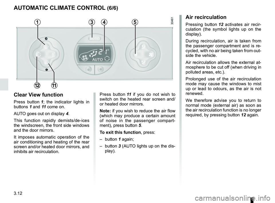
Clear View function
Press button 1; the indicator lights in
buttons 1 and 11 come on.
AUTO goes out on display 4.
This function rapidly demists/de-ices
the windscreen, the front side windows
and the door mirrors.
It imposes automatic operation of the
air conditioning and heating of the rear
screen and/or heated door mirrors, and
inhibits air recirculation. Press button
11 if you do not wish to
switch on the heated rear screen and/
or heated door mirrors.
Note: if you wish to reduce the air flow
(which may produce a certain amount
of noise in the passenger compart-
ment), press button 5.
To exit this function , press:
– button 1 again;
– button 3 (AUTO lights up on the dis-
play).
Air recirculation
Pressing button 12 activates air recir-
culation (the symbol lights up on the
display).
During recirculation, air is taken from
the passenger compartment and is re-
cycled, with no air being taken from out-
side the vehicle.
Air recirculation allows the external at-
mosphere to be cut off (when driving in
polluted areas, etc.).
Prolonged use of the air recirculation
mode may cause the windows to mist
up or lead to odours, as the air is not
renewed.
We therefore advise you to return to
normal mode (external air) as soon as
the air recirculation function is no longer
required, by pressing button 12 again.
AUTOMATIC CLIMATE CONTROL (6/6)
35
12
4
11
1
Page 183 of 290
3.17
INTERIOR LIGHTING
12
Courtesy light
Use switch 1 to:
– permanent lighting;
– intermittent lighting, which comes on when a door is opened. It goes out
when the doors concerned are prop-
erly closed;
– immediate switching off.
Map reading lights(depending on the vehicle)
Move switch 2.
Note
Remote unlocking of the doors triggers
timed lighting of the passenger com-
partment.
If one of the front or rear doors is
opened, the timed lighting will start
again.
Then the courtesy light and the luggage
compartment light dim and go out. The
lighting timer will cut out for various rea-
sons:
– if a door has been open for 15 min- utes;
– if all the doors have been closed for 15 seconds:
– when the ignition is switched on.
Rear light 3
Turn switch 4 to:
– switch on continuous lighting;
– switch on intermittent lighting when one of the rear doors is opened. The
lights only go out when the doors are
correctly closed;
– force the lights off.
3
4
Page 185 of 290

3.19
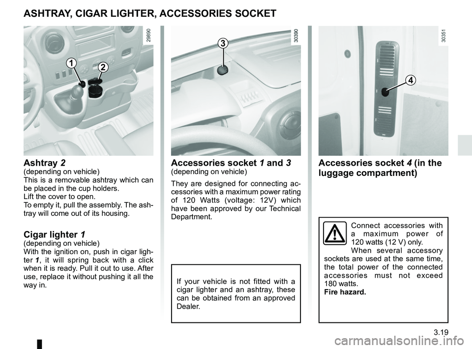
Accessories socket 4 (in the
luggage compartment)
ASHTRAY, CIGAR LIGHTER, ACCESSORIES SOCKET
Accessories socket 1 and 3(depending on vehicle)
They are designed for connecting ac-
cessories with a maximum power rating
of 120 Watts (voltage: 12V) which
have been approved by our Technical
Department.Ashtray 2(depending on vehicle)
This is a removable ashtray which can
be placed in the cup holders.
Lift the cover to open.
To empty it, pull the assembly. The ash-
tray will come out of its housing.
Cigar lighter 1(depending on vehicle)
With the ignition on, push in cigar ligh-
ter 1, it will spring back with a click
when it is ready. Pull it out to use. After
use, replace it without pushing it all the
way in.
If your vehicle is not fitted with a
cigar lighter and an ashtray, these
can be obtained from an approved
Dealer.
Connect accessories with
a maximum power of
120 watts (12 V) only.
When several accessory
sockets are used at the same time,
the total power of the connected
accessories must not exceed
180 watts.
Fire hazard.
12
4
3
Page 196 of 290
3.30
TRANSPORTING OBJECTS (2/2)
Towing
Fitting the towing ball
Position the ball within the range of
height D, which must be between 350
and 420 mm, with the vehicle laden.
Tighten bolts 3, observing a tightening
torque of 196 Nm (Newton metres).
33
C
Front-wheel drive, standard wheels
C = 1,110 mm.
Rear-wheel drive, standard wheels
C = 1,760 mm.
Rear-wheel drive, dual wheels
C = 1,753 mm.
D
If the towbar ball obscures the regis-
tration plate or the rear fog lights, it
should be removed when not in use.
In all cases, comply with local legis-
lation.
Permissible nose weight, maxi-
mum permissible towing weight,
braked and unbraked: refer to
the information on “Weights” in
Section 6.
Choice and fitting of towing
equipment
Maximum weight of towing equip-
ment: 26 kg
For fitting and conditions of use,
refer to the equipment’s fitting ins-
tructions.
Please keep these instructions with
the rest of the vehicle documenta-
tion.
Page 198 of 290
4.2
BONNET (1/2)
To open the bonnet, pull handle 1.
Unlocking the bonnet catch
To unlock, pull control 2.
In the event of even a slight
impact involving the radia-
tor grille or bonnet, have the
bonnet lock checked by an
authorised dealer as soon as pos-
sible.
1
2
Please note when work-
ing close to the engine that
it may be hot. In addition,
the engine cooling fan may
start at any moment. The
warning light in the engine compart-
ment reminds you of this.
Risk of injury.Before performing any
action in the engine com-
partment, the ignition must
be switched off (please see
the information on “Starting, stop-
ping the engine” in Section 2).
Page 200 of 290

4.4
ENGINE OIL LEVEL: general information (1/2)
If the level is at the minimum
The “TOP-UP OIL LEVEL” message
and warning light
© are displayed
on the instrument panel.
It is vital to top up the oil as soon as
possible.
The display only warns the
driver if the oil level is at the
minimum level. It does not
inform the driver that the oil
level has exceeded the maximum
level as this can only be measured
using a dipstick.
It is normal for an engine to use oil for
lubrication and cooling of moving parts
and it is normal to top up the level be-
tween oil changes.
However, contact an approved Dealer if
more than 0.5 litres is being consumed
every 600 miles (1,000 km) after the
running in period.
Oil change frequency: check the oil
level from time to time and certainly
before any long journey to avoid the
risk of damaging your engine.
Reading the oil level
The oil level should be read with the ve-
hicle on level ground, after the engine
has been switched off for some time.
The dipstick must be used to read
the exact oil level and make sure
that the maximum level has not been
exceeded (risk of engine damage).
Refer to the following pages.
The instrument panel display only
alerts the driver when the oil level is at
its minimum.
A
1
2
Minimum oil level display A
If the level is above the minimum
level
The “OIL LEVEL” message appears on
the display, accompanied by squares
indicating the level. These squares di-
sappear as the level drops and they are
replaced by dashes.
To switch to trip computer reading,
press button 1 or 2 again.