Page 18 of 337

KEYS
Key Fob
Your vehicle uses a key start ignition system. The ignition
system consists of a key fob with a Remote Keyless Entry
(RKE) and an ignition switch.
The key fob contains an integrated mechanical key. To use
the mechanical key, simply push the mechanical key re-
lease button.
The vehicle is supplied with a code card containing key
code numbers to order duplicate keys, and the authorized
dealer that sold you your new vehicle has the key code
numbers for your vehicle locks. These numbers can be
used to order duplicate keys.Remote Keyless Entry (RKE)
This system allows you to lock or unlock the doors from
distances up to approximately 66 ft (20 m) using a hand-
held key fob. The key fob does not need to be pointed at the
vehicle to activate the system.
NOTE:
The key fob may not be able to be detected by the
vehicle if it is located next to a mobile phone, laptop or
other electronic device; these devices may block the key
fob’s wireless signal.
Key Fob With Integrated Mechanical Key
16 GETTING TO KNOW YOUR VEHICLE
Page 64 of 337

WARNING!
To avoid serious injury or death:
•Only devices designed for use in this type of outlet
should be inserted into any 12 Volt outlet.
• Do not touch with wet hands.
(Continued)
WARNING! (Continued)
•Close the lid when not in use and while driving the
vehicle.
• If this outlet is mishandled, it may cause an electric
shock and failure.
CAUTION!
• Many accessories that can be plugged in draw power
from the vehicle’s battery, even when not in use (i.e.,
cellular phones, etc.). Eventually, if plugged in long
enough, the vehicle’s battery will discharge suffi-
ciently to degrade battery life and/or prevent the
engine from starting.
• Accessories that draw higher power (i.e., coolers,
vacuum cleaners, lights, etc.) will degrade the battery
even more quickly. Only use these intermittently and
with greater caution.
• After the use of high power draw accessories, or long
periods of the vehicle not being started (with acces-
sories still plugged in), the vehicle must be driven a
sufficient length of time to allow the generator to
recharge the vehicle’s battery.
Power Outlet Fuse Locations
1 — F14 Fuse 20 A Yellow Front Power Outlet
2 — F09 Fuse 15 A Blue Rear Power Outlet 62 GETTING TO KNOW YOUR VEHICLE
Page 291 of 337

MULTIMEDIA
CONTENTS
�UCONNECT RADIOS ....................290
� CYBERSECURITY ....................... .290
� UCONNECT SETTINGS ...................291
▫ Customer Programmable Features — Uconnect 3
Settings ............................. .292
� STEERING WHEEL AUDIO CONTROLS .......304
▫ Radio Operation ....................... .304
▫ Player Operation ...................... .304
� IPOD/USB/MP3 CONTROL — IF EQUIPPED . . . .304
▫ USB Charging Port ..................... .305
� RADIO OPERATION AND MOBILE PHONES . . .306
▫ Regulatory And Safety Information ..........306
� UCONNECT VOICE RECOGNITION .........307▫
Introducing Uconnect ....................307
▫ Get Started .......................... .307
▫ Basic Voice Commands ...................309
▫ Radio .............................. .309
▫ Media .............................. .310
▫ Phone ...............................311
▫ Voice Text Reply ...................... .312
▫ General Information .....................313
▫ Additional Information ...................313
� CD/DVD DISC MAINTENANCE ............314
10
Page 293 of 337

NOTE:
•FCA or your dealer may contact you directly regarding
software updates.
• To help further improve vehicle security and minimize
the potential risk of a security breach, vehicle owners
should:
• Routinely check www.driveuconnect.com/software-
update to learn about available Uconnect software
updates.
• Only connect and use trusted media devices (e.g.
personal mobile phones, USBs, CDs).
Privacy of any wireless and wired communications cannot
be assured. Third parties may unlawfully intercept infor-
mation and private communications without your consent.
For further information, refer to “Onboard Diagnostic
System (OBD II) Cybersecurity” in “Getting To Know Your
Instrument Panel”.
UCONNECT SETTINGS
The Uconnect system uses a combination of buttons on the
touchscreen and buttons on the faceplate located on the
center of the instrument panel that allows you to access and change the customer programmable features. Many
features can vary by vehicle.
CAUTION!
Do NOT attach any object to the touchscreen, doing so
can result in damage to the touchscreen.
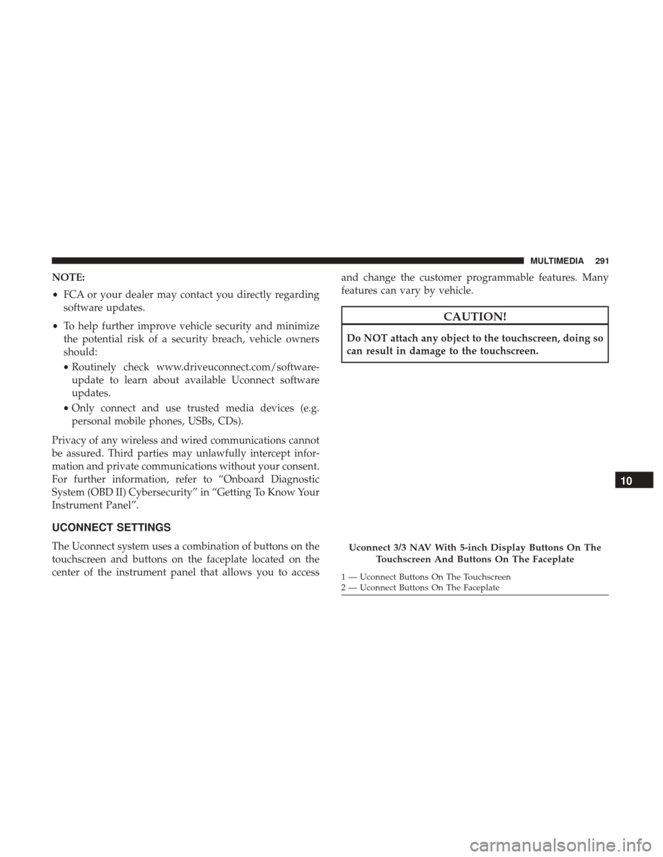
Uconnect 3/3 NAV With 5-inch Display Buttons On The
Touchscreen And Buttons On The Faceplate
1 — Uconnect Buttons On The Touchscreen
2 — Uconnect Buttons On The Faceplate
10
MULTIMEDIA 291
Page 294 of 337

NOTE:The NAV button in the middle of your Uconnect
radio may also contain the word COMPASS
Customer Programmable Features — Uconnect 3
Settings
Push the Settings button on the faceplate to display the
menu setting screen. In this mode the Uconnect system
allows you to access programmable features that may be
equipped such as Language, Display, Units (if equipped),
Voice, Clock, Safety & Driving Assistance (if equipped),
Lights, Doors & Locks, Engine off Options, Audio, Phone
(if equipped), SiriusXM Setup (if equipped), Radio Setup,
Restore Settings and Clear Personal Data. NOTE:
•
Only one category may be selected at a time.
• The Back arrow will change into a Done button if any
changes are made.
When making a selection, press the button on the touch-
screen to enter the desired mode. Once in the desired
mode, press and release the preferred setting. Once the
setting is complete, either press the Back Arrow button on
the touchscreen or the Back button on the faceplate to
return to the previous menu or press the X button on the
touchscreen to return to the Main Settings screen. Pressing
the Up or Down Arrow buttons on the touchscreen on the
right side of the screen will allow you to toggle up or down
through the available settings.
292 MULTIMEDIA
Page 302 of 337
Setting NameSelectable Options
Auto Play On Off
NOTE: The Auto Play feature allows an media device to begin playing when the media device is plugged in. To
make your selection, press the On or Off buttons to activate or deactivate Auto Play.
AUX Volume Offset +–
NOTE: This feature provides the ability to tune the audio level for portable devices connected through the AUX in-
put.
Phone
After pressing the “Phone” button on the touchscreen, the
following settings will be available:
Setting Name Selectable Options
Paired Phones/Devices List of Paired Phones/Devices
NOTE:
This feature shows which phones are paired to the Phone system. For further information, refer to the Uconnect
Owner ’s Manual Supplement.
300 MULTIMEDIA
Page 307 of 337
iPod control supports Mini, 4G, Photo, Nano, 5G iPod and
iPhone devices. Some iPod software versions may not fully
support the iPod control features. Please visit Apple’s
website for software updates.
For further information, refer to the Uconnect Owner ’s
Manual Supplement.
USB Charging Port
The USB connector port can be used for charging purposes
only. Use the connection cable to connect an iPod or
external USB device to the vehicle’s USB charging port
which is located next to the 12V power outlet near the cup
holder on passenger side.
NOTE:If the device battery to be charged is completely
depleted, it may take awhile to charge.
USB Port And AUX Jack
1 — USB Port
2 — AUX Audio Jack
Passenger Compartment USB Charging Port
10
MULTIMEDIA 305
Page 308 of 337

WARNING!
Do not plug in or remove the iPod or external device
while driving. Failure to follow this warning could
result in a collision.
RADIO OPERATION AND MOBILE PHONES
Under certain conditions, the mobile phone being on in
your vehicle can cause erratic or noisy performance from
your radio. This condition may be lessened or eliminated
by relocating the mobile phone. This condition is not
harmful to the radio. If your radio performance does not
satisfactorily “clear” by the repositioning of the phone, it is
recommended that the radio volume be turned down or off
during mobile phone operation when not using Uconnect
(if equipped).
Regulatory And Safety Information
USA/CANADA
Exposure to Radio Frequency RadiationThe radiated output power of the internal wireless radio is
far below the FCC and IC radio frequency exposure limits.
Nevertheless, the wireless radio will be used in such a
manner that the radio is 20 cm or further from the human
body.
The internal wireless radio operates within guidelines
found in radio frequency safety standards and recommen-
dations, which reflect the consensus of the scientific com-
munity.
The radio manufacturer believes the internal wireless radio
is safe for use by consumers. The level of energy emitted is
far less than the electromagnetic energy emitted by wire-
less devices such as mobile phones. However, the use of
wireless radios may be restricted in some situations or
environments, such as aboard airplanes. If you are unsure
of restrictions, you are encouraged to ask for authorization
before turning on the wireless radio.
306 MULTIMEDIA