2018 PEUGEOT 5008 change wheel
[x] Cancel search: change wheelPage 201 of 364
199
Conditions for operation
The speed of the vehicle must be between
40 and 112 mph (65 and 180 km/h).
The carriageway must have at least one lane
marking (solid or broken) on the ground.
The driver must hold the wheel with both
hands.
The change of trajectory must not be
accompanied by operation of the direction
indicators.
The ESC system must be activated.
This system is a
driving aid which cannot,
in any circumstances, replace the need
for vigilance on the part of the driver.
The driver should remain in control of the
vehicle in all circumstances.
The system helps the driver only when
there is a
risk of the vehicle involuntarily
wandering from the lane it is being driven
on. It does not manage the safe driving
distance, the speed of the vehicle or the
brakes.
The driver must hold the steering wheel
with both hands in a
way that allows
control to be taken back in circumstances
where the system is not able to inter vene
(if lane markings disappear, for example).
It is necessary to obser ve the driving
regulations and take a
break every two
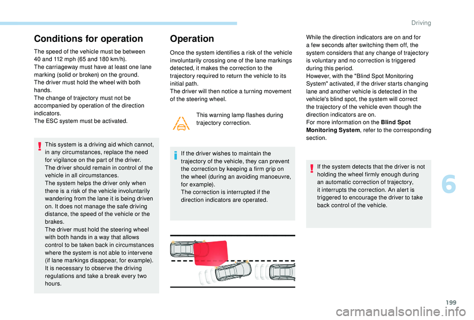
hours. This warning lamp flashes during
trajectory correction.
If the driver wishes to maintain the
trajectory of the vehicle, they can prevent
the correction by keeping a
firm grip on
the wheel (during an avoiding manoeuvre,
for example).
The correction is interrupted if the
direction indicators are operated. If the system detects that the driver is not
holding the wheel firmly enough during
an automatic correction of trajectory,
it interrupts the correction. An alert is
triggered to encourage the driver to take
back control of the vehicle.
Operation
Once the system identifies a risk of the vehicle
i nvoluntarily crossing one of the lane markings
detected, it makes the correction to the
trajectory required to return the vehicle to its
initial path.
The driver will then notice a
turning movement
of the steering wheel. While the direction indicators are on and for
a
few seconds after switching them off, the
system considers that any change of trajectory
is voluntary and no correction is triggered
during this period.
However, with the "Blind Spot Monitoring
System" activated, if the driver starts changing
lane and another vehicle is detected in the
vehicle's blind spot, the system will correct
the trajectory of the vehicle even though the
direction indicators are on.
For more information on the Blind Spot
Monitoring System , refer to the corresponding
section.
6
Driving
Page 210 of 364
208
The display is immediately updated with the
type of view selected.
The state of the system is not kept in memory
when the ignition is switched off.
Principle of operation
Using one or two cameras, the close
surroundings of the vehicle are recorded whilst
manoeuvring at low speed.
An image from above your vehicle in its close
surroundings is created in real time, as the
vehicle manoeuvre progresses.
This representation facilitates the alignment of
your vehicle when parking and allows obstacles
close to the vehicle to be seen.
This image is automatically deleted if the
vehicle remains stationary for too long.When the function is activated, it is possible
that the central view is not displayed. If the
system is activated after the vehicle has
already been driven, the central view may be
completely displayed.
This system is a visual aid that cannot in
any circumstances replace the need for
vigilance on the part of the driver.
The images provided by the camera(s)
may be distorted by the relief.
In the presence of areas in shade, or in
conditions of bright sunlight or inadequate
lighting, the image may be darkened and
with lower contrast.
Recommendations on care
In bad or wintry weather, ensure that the
sensors and camera lenses are not covered
with mud, ice or snow.
Check the cleanliness of the camera lenses
regularly.
If necessary, clean the cameras with a
soft, dry
cloth.
When washing your vehicle at high pressure,
direct the lance at least 30
cm away from the
cameras and parking aid sensors.
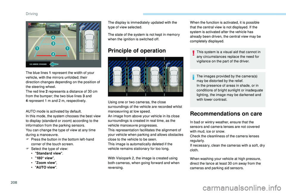
The blue lines 1
represent the width of your
vehicle, with the mirrors unfolded; their
direction changes depending on the position of
the steering wheel.
The red line 2
represents a
distance of 30
cm
from the bumper; the two blue lines 3
and
4
represent 1
m and 2
m, respectively.
AUTO mode is activated by default.
In this mode, the system chooses the best view
to display (standard or zoom) according to the
information from the parking sensors.
You can change the type of view at any time
during a
manoeuvre.
F
P
ress the button in the bottom left-hand
corner of the touch screen.
F
Sel
ect the type of view:
•
" Standard view ".
•
" 180° view ",
•
" Zoom view ",
•
" AUTO view ". With Visiopark 2, the image is created using
both cameras, when going for ward and when
reversing.
Driving
Page 211 of 364
209
AUTO modeStandard view Zoom viewVisiopark 1
Rear vision
To activate the camera, located in the tailgate,
engage reverse and keep the speed of the
vehicle below 6
mph (10 km/h).
The system is deactivated:
-
a
utomatically above about 6 mph (10 km/h),
-
a
utomatically on opening the tailgate,
-
w
hen shifting out of reverse (the image
remains displayed for 7
seconds),
-
b
y pressing the red cross in the top left-
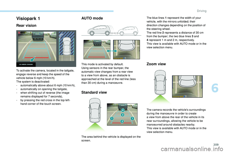
hand corner of the touch screen. This mode is activated by default.
Using sensors in the rear bumper, the
automatic view changes from a
rear view
to a
view from above, as an obstacle is
approached at the level of the red line (less
than 30
cm) during a manoeuvre.The blue lines 1
represent the width of your
vehicle, with the mirrors unfolded; their
direction changes depending on the position of
the steering wheel.
The red line 2 represents a distance of 30 cm
from the bumper; the two blue lines 3 and
4 represent 1 m and 2 m, respectively.
This view is available with AUTO mode or in the
view selection menu.
The area behind the vehicle is displayed on the
screen. The camera records the vehicle's surroundings
during the manoeuvre in order to create
a
view from above the rear of the vehicle in its
near surroundings, allowing the vehicle to be
manoeuvred around obstacles nearby.
This view is available with AUTO mode or in the
view selection menu.
6
Driving
Page 213 of 364
211
With the engine running and the
speed below 12 mph (20 km/h), the
system is activated via the Vehicle/
Driving menu of the touch screen:
The system is deactivated:
-
a
utomatically above about 19 mph (30 km/h)
(the image disappears temporarily from
12
mph (20 km/h)),
-
b
y pressing the red cross in the top left-
hand corner of the touch screen.
AUTO mode Standard view
F Select "
Panoramic visual aid ".
AUTO mode is displayed by default, with front
vision, if the gearbox is in neutral or with a
gear
engaged, or with rear vision, if reverse is
engaged.
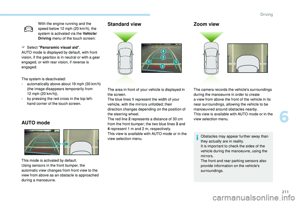
This mode is activated by default.
Using sensors in the front bumper, the
automatic view changes from front view to the
view from above as an obstacle is approached
during a
manoeuvre.
Zoom view
Obstacles may appear further away than
they actually are in reality.
It is important to check the sides of the
vehicle during the manoeuvre, using the
mirrors.
The front and rear parking sensors also
provide information on the vehicle's
surroundings.
The area in front of your vehicle is displayed in
the screen.
The blue lines 1
represent the width of your
vehicle, with the mirrors unfolded; their
direction changes depending on the position of
the steering wheel.
The red line 2
represents a
distance of 30
cm
from the front bumper; the two blue lines 3
and
4
represent 1
m and 2
m, respectively.
This view is available with AUTO mode or in the
view selection menu. The camera records the vehicle's surroundings
during the manoeuvre in order to create
a
view from above the front of the vehicle in its
near surroundings, allowing the vehicle to be
manoeuvred around obstacles nearby.
This view is available with AUTO mode or in the
view selection menu.
6
Driving
Page 238 of 364
236
On a new vehicle, the first particle
f ilter regeneration operations may be
accompanied by a "burning" smell, which
is per fectly normal.
Following prolonged operation of the
vehicle at very low speed or at idle,
you may, in exceptional circumstances,
notice the emission of water vapour at the
exhaust on acceleration. This does not
affect the behaviour of the vehicle or the
environment.
Manual gearbox
The gearbox does not require any
maintenance (no oil change).
Automatic gearbox
The gearbox does not require any
maintenance (no oil change).
Brake pads
Brake wear depends on the style
of driving, particularly in the case
of vehicles used in town, over short
distances. It may be necessary to
have the condition of the brakes
checked, even between vehicle
services.
Unless there is a
leak in the circuit, a drop in
the brake fluid level indicates that the brake
pads are worn.
Brake disc wear
For information on checking brake
disc wear, contact a PEUGEOT
dealer or a
qualified workshop.
Electric parking brake
This system does not require any
routine servicing. However, in the
event of a problem, have the system
checked by a
PEUGEOT dealer or
a
qualified workshop. For more information on the Electric
parking brake
, refer to the corresponding
section.
Wheels and tyres
The pressure must be checked on
all tyres, including the spare wheel,
when the tyres are "cold", at least
once a
month and before a long
j o u r n ey.
The pressures given on the tyre pressure label
are valid for "cold" tyres. If you have driven for
more than 10
minutes or more than 6 miles
(10
kilometres) at more than 31 mph (50 km/h),
0.3
bar (30 kPa) should be added to the values
given on the label.
Under-inflation increases fuel consumption.
Non-compliant tyre pressure causes premature
wear on tyres and has an adverse effect on the
vehicle's road holding – Risk of an accident!
Driving with worn or damaged tyres reduces
braking efficiency and control of the vehicle's
steering. Regular inspections of the condition
of tyres (tread and sides) and rims are
recommended as well as making sure that
valves are fitted.
Practical information
Page 244 of 364
242
For versions with a spare wheel:
For more information on the Spare wheel, refer
to the corresponding section. All of these tools are specific to your
vehicle and may vary depending on
equipment.
Do not use them for any other purposes.
The jack must only be used to change
a
wheel with a damaged or punctured tyre.
Do not use any jack other than the one
supplied with this vehicle.
If the vehicle does not have its original
jack, contact a PEUGEOT dealer or
a qualified workshop to obtain the correct
jack for it.
The jack meets European standards,
as defined in the Machinery Directive
2006/42/CE.
The jack does not require any
maintenance.
Access to the tools
Some of the tools are stored beneath the floor
against the boot sill.
The left box contains the wheelbrace and its
extension piece.
The right box contains the wheel chocks and
the towing eye.
To gain access to them:
F
o
pen the boot,
F
fo
ld the concertina boards back,
F
i
nstall the third row seats,
F
u
nclip the required tools from the boot sill
trim.
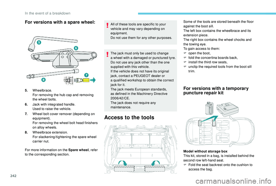
5. Wheelbrace.
For removing the hub cap and removing
the wheel bolts.
6. Jack with integrated handle.
Used to raise the vehicle.
7. Wheel bolt cover remover (depending on
equipment).
For removing the wheel bolt head finishers
on alloy wheels.
8. Wheelbrace extension.
For slackening/tightening the spare wheel
carrier nut.
For versions with a temporary
p uncture repair kit
Model without storage box
This kit, stored in a
bag, is installed behind the
second row left-hand seat.
F
F
old the seat backrest onto the cushion to
access the bag.
In the event of a breakdown
Page 248 of 364
246
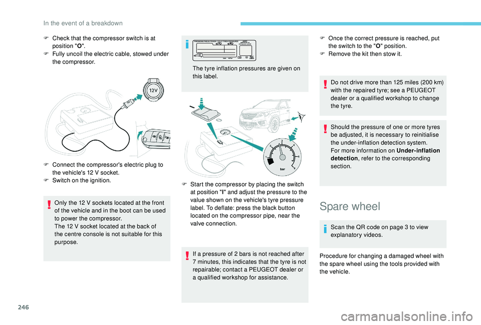
F Check that the compressor switch is at position " O".
F
F
ully uncoil the electric cable, stowed under
the compressor.
Only the 12
V sockets located at the front
of the vehicle and in the boot can be used
to power the compressor.
The 12
V socket located at the back of
the centre console is not suitable for this
purpose.
F
C
onnect the compressor's electric plug to
the vehicle's 12
V socket.
F
S
witch on the ignition. The tyre inflation pressures are given on
this label.
If a
pressure of 2 bars is not reached after
7
minutes, this indicates that the tyre is not
repairable; contact a
PEUGEOT dealer or
a
qualified workshop for assistance.F
O nce the correct pressure is reached, put
the switch to the " O" position.
F
R
emove the kit then stow it.
Do not drive more than 125
miles (200 km)
with the repaired tyre; see a
PEUGEOT
dealer or a
qualified workshop to change
the tyre.
Should the pressure of one or more tyres
be adjusted, it is necessary to reinitialise
the under-inflation detection system.
For more information on Under-inflation
detection , refer to the corresponding
section.
F
S
tart the compressor by placing the switch
at position " I" and adjust the pressure to the
value shown on the vehicle's tyre pressure
label. To deflate: press the black button
located on the compressor pipe, near the
valve connection.
Spare wheel
Scan the QR code on page 3 to view
e xplanatory videos.
Procedure for changing a
damaged wheel with
the spare wheel using the tools provided with
the vehicle.
In the event of a breakdown
Page 251 of 364
249
Removing a wheel
Wheel with wheel trim
When removing the wheel, first remove
the wheel trim by pulling at the valve
aperture using the wheelbrace.
When refitting the wheel , after tightening
the wheel bolts, refit the wheel trim,
starting by placing its aperture in line with
the valve and then pushing it into place all
round its edge with the palm of your hand. Parking the vehicle
Immobilise the vehicle where it does not
block traffic: the ground must be level,
stable and non-slippery.
Apply the parking brake, unless it is
programmed to be in automatic mode;
switch off the ignition and with a
manual
gearbox, engage first gear so as to lock
the wheels.
Apply the parking brake, unless it is
programmed to be in automatic mode;
switch off the ignition and with an
automatic gearbox, select mode P so as to
lock the wheels.
Check that the parking brake warning
lamps in the instrument panel are on fixed
(not flashing).
The occupants must get out of the vehicle
and wait where they are safe.
If necessary, place a
chock under the
wheel diagonally opposite the wheel to be
changed.
Never go underneath a
vehicle raised
using a
jack; use an axle stand.
F
T
ighten it fully. When the cable is
completely reeled in, turning the nut no
longer encounters resistance.
F
C
heck that the wheel is properly flattened
against the floor.
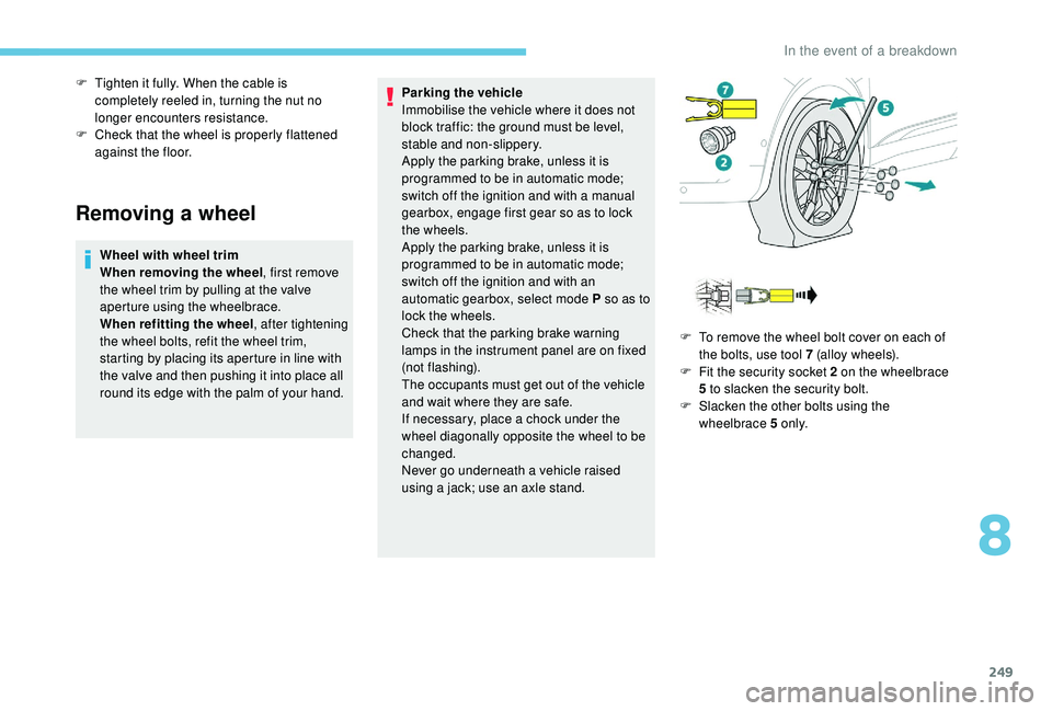
F
T
o remove the wheel bolt cover on each of
the bolts, use tool 7 (alloy wheels).
F
F
it the security socket 2 on the wheelbrace
5
to slacken the security bolt.
F
S
lacken the other bolts using the
wheelbrace 5
o n l y.
8
In the event of a breakdown