2018 Peugeot 308 boot
[x] Cancel search: bootPage 206 of 360
204
- Certain materials (fabrics) absorb sound waves: pedestrians may not be detected.
-
A
ccumulated snow or dead leaves on the
road sur face can inter fere with the vehicle's
sensors.
-
A f
ront or rear impact to the vehicle can
distort the settings of the sensors, which is
not always detected by the system: distance
measurements may be incorrect.
-
T
he tilting of the vehicle if the boot is
very loaded can affect the distance
measurements.
-
T
he sensors may be affected by poor
weather conditions (heavy rain, thick fog,
snowfall, etc.).
Recommendations on care
In bad or wintry weather, ensure that the
sensors are not covered with mud, ice or
snow. When reverse gear is engaged, an
audible signal (long beep) indicates that
the sensors may be dirty. High pressure washing
When washing your vehicle, direct the
lance at least 30
cm away from the
sensors.
Operating fault
If a fault occurs when shifting
to reverse, this warning lamp
comes on in the instrument panel,
accompanied by a message and an
audible signal (short beep).
Contact a PEUGEOT dealer or a qualified
workshop
to have the system checked.
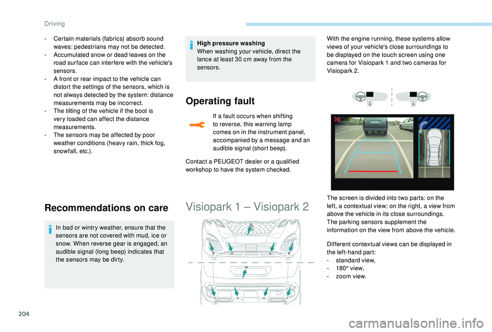
Visiopark 1 – Visiopark 2
Different contextual views can be displayed in
the left-hand part:
-
s
tandard view,
-
1
80° view,
-
z
oom view.
With the engine running, these systems allow
views of your vehicle's close surroundings to
be displayed on the touch screen using one
camera for Visiopark 1 and two cameras for
Visiopark 2.
The screen is divided into two parts: on the
left, a contextual view; on the right, a view from
above the vehicle in its close surroundings.
The parking sensors supplement the
information on the view from above the vehicle.
Driving
Page 225 of 360
223
Maintenance
Correct operation is only possible if the towball
and its carrier are kept clean.
Before cleaning the vehicle with a high-
pressure jet wash, the towball must be removed
and the protective plug fitted to the carrier.Apply the label provided to a clearly visible
area, close to the carrier or in the boot.
Go to a PEUGEOT dealer or a qualified
workshop for any work on the towbar
system.
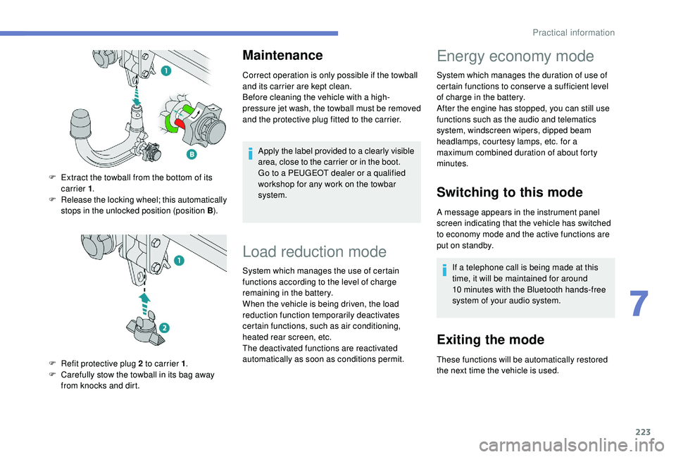
F
E
xtract the towball from the bottom of its
carrier 1 .
F
R
elease the locking wheel; this automatically
stops in the unlocked position (position B ).
F
R
efit protective plug 2 to carrier 1 .
F
C
arefully stow the towball in its bag away
from knocks and dirt.
Load reduction mode
System which manages the use of certain
functions according to the level of charge
remaining in the battery.
When the vehicle is being driven, the load
reduction function temporarily deactivates
certain functions, such as air conditioning,
heated rear screen, etc.
The deactivated functions are reactivated
automatically as soon as conditions permit.
Energy economy mode
System which manages the duration of use of
certain functions to conser ve a sufficient level
of charge in the battery.
After the engine has stopped, you can still use
functions such as the audio and telematics
system,
windscreen wipers, dipped beam
headlamps,
courtesy lamps, etc. for a
maximum combined duration of about forty
minutes.
Switching to this mode
A message appears in the instrument panel
screen indicating that the vehicle has switched
to economy mode and the active functions are
put on standby.
If a telephone call is being made at this
time, it will be maintained for around
10
minutes with the Bluetooth hands-free
system of your audio system.
Exiting the mode
These functions will be automatically restored
the next time the vehicle is used.
7
Practical information
Page 240 of 360
238
With 1.5 BlueHDi and 2.0
BlueHDi 180 S&S engines
F Fill the fuel tank with at least 5 litres of
Diesel.
F
S
witch on the ignition (without starting the
engine).
F
W
ait around 1 minute and switch off the
ignition.
F
O
perate the starter to run the engine.
If the engine does not start, repeat the
procedure.
With 2.0 HDi engines
F Put it back in place, clip in the cover and ensure it is clipped in.
F
C
lose the bonnet.
Tool kit
This is a set of tools provided with the vehicle.
Its content depends on your vehicle's
equipment:
-
t
emporary puncture repair kit,
-
spar
e wheel.
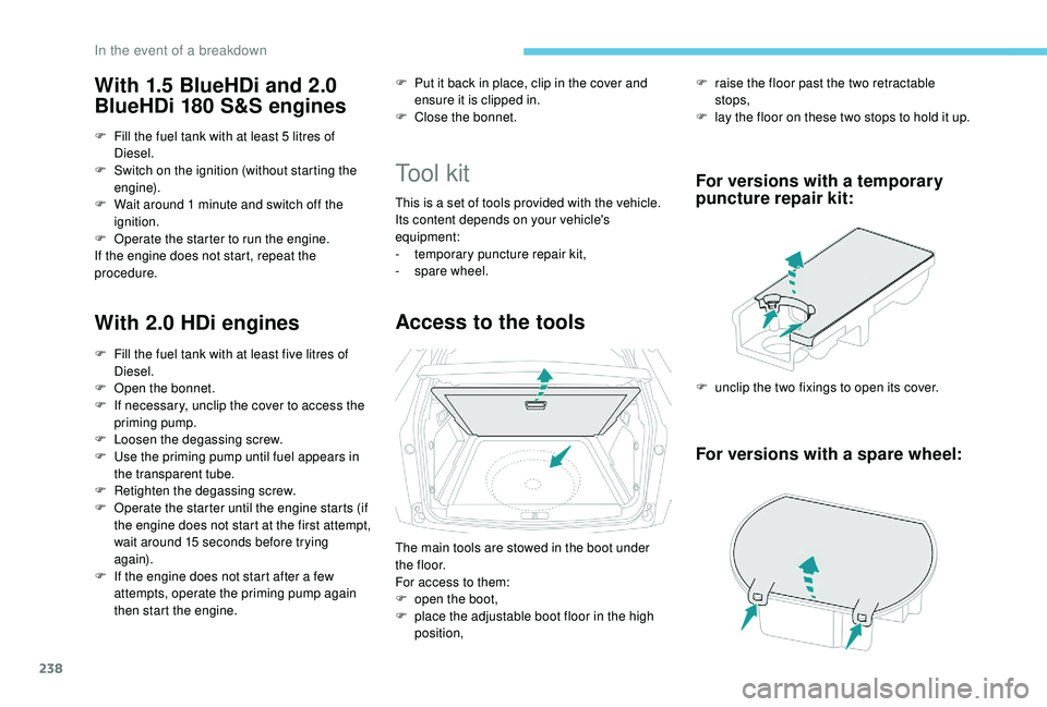
Access to the tools
F raise the floor past the two retractable stops,
F
l
ay the floor on these two stops to hold it up.
For versions with a temporary
puncture repair kit:
F unclip the two fixings to open its cover.
For versions with a spare wheel:
F Fill the fuel tank with at least five litres of Diesel.
F
O
pen the bonnet.
F
I
f necessary, unclip the cover to access the
priming pump.
F
L
oosen the degassing screw.
F
U
se the priming pump until fuel appears in
the transparent tube.
F
R
etighten the degassing screw.
F
O
perate the starter until the engine starts (if
the engine does not start at the first attempt,
wait around 15
seconds before trying
again).
F
I
f the engine does not start after a few
attempts, operate the priming pump again
then start the engine. The main tools are stowed in the boot under
t h e f l o o r.
For access to them:
F
o
pen the boot,
F
p
lace the adjustable boot floor in the high
position,
In the event of a breakdown
Page 243 of 360
241
Avoid removing any foreign bodies which
have penetrated into the tyre.
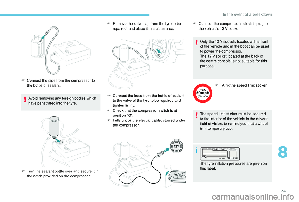
F
C
onnect the pipe from the compressor to
the bottle of sealant. F
R
emove the valve cap from the tyre to be
repaired, and place it in a clean area.
F
C
heck that the compressor switch is at
position " O".
F
F
ully uncoil the electric cable, stowed under
the compressor. Only the 12
V sockets located at the front
of the vehicle and in the boot can be used
to power the compressor.
The 12 V socket located at the back of
the centre console is not suitable for this
purpose.
F
A
ffix the speed limit sticker.
The speed limit sticker must be secured
to the interior of the vehicle in the driver's
field of vision, to remind you that a wheel
is in temporary use.
F
T
urn the sealant bottle over and secure it in
the notch provided on the compressor. F
C onnect the hose from the bottle of sealant
to the valve of the tyre to be repaired and
tighten firmly. F
C
onnect the compressor's electric plug to
the vehicle's 12 V socket.
The tyre inflation pressures are given on
this label.
8
In the event of a breakdown
Page 245 of 360
243
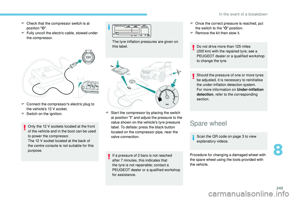
F Check that the compressor switch is at position " O".
F
F
ully uncoil the electric cable, stowed under
the compressor.
Only the 12
V sockets located at the front
of the vehicle and in the boot can be used
to power the compressor.
The 12
V socket located at the back of
the centre console is not suitable for this
purpose.
F
C
onnect the compressor's electric plug to
the vehicle's 12
V socket.
F
S
witch on the ignition. The tyre inflation pressures are given on
this label.
If a pressure of 2
bars is not reached
after 7
minutes, this indicates that
the tyre is not repairable; contact a
PEUGEOT dealer or a qualified workshop
for assistance. F
O nce the correct pressure is reached, put
the switch to the " O" position.
F
R
emove the kit then stow it.
Do not drive more than 125
miles
(200
km) with the repaired tyre; see a
PEUGEOT dealer or a qualified workshop
to change the tyre.
Should the pressure of one or more tyres
be adjusted, it is necessary to reinitialise
the under-inflation detection system.
For more information on Under-inflation
detection , refer to the corresponding
section.
F
S
tart the compressor by placing the switch
at position " I" and adjust the pressure to the
value shown on the vehicle's tyre pressure
label. To deflate: press the black button
located on the compressor pipe, near the
valve connection.
Spare wheel
Scan the QR code on page 3 to view
explanatory videos.
Procedure for changing a damaged wheel with
the spare wheel using the tools provided with
the vehicle.
8
In the event of a breakdown
Page 246 of 360
244
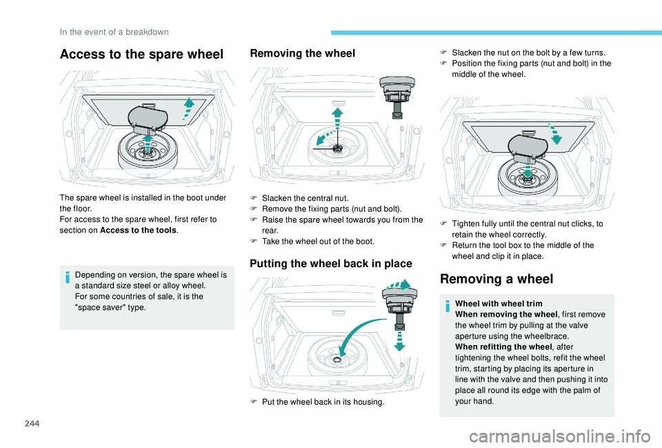
Access to the spare wheel
The spare wheel is installed in the boot under
t h e f l o o r.
For access to the spare wheel, first refer to
section on Access to the tools.
Depending on version, the spare wheel is
a standard size steel or alloy wheel.
For some countries of sale, it is the
"space saver" type.
Removing the wheel
F Slacken the central nut.
F R emove the fixing parts (nut and bolt).
F
R
aise the spare wheel towards you from the
r e a r.
F
T
ake the wheel out of the boot.
Putting the wheel back in place
Removing a wheel
Wheel with wheel trim
When removing the wheel , first remove
the wheel trim by pulling at the valve
aperture using the wheelbrace.
When refitting the wheel , after
tightening the wheel bolts, refit the wheel
trim, starting by placing its aperture in
line with the valve and then pushing it into
place all round its edge with the palm of
your hand.
F
P
ut the wheel back in its housing. F
S
lacken the nut on the bolt by a few turns.
F
P
osition the fixing parts (nut and bolt) in the
middle of the wheel.
F
T
ighten fully until the central nut clicks, to
retain the wheel correctly.
F
R
eturn the tool box to the middle of the
wheel and clip it in place.
In the event of a breakdown
Page 249 of 360
247
After changing a wheel
Put the punctured wheel in the boot or,
depending on version, remove the central cover
first to store it beneath the floor in place of the
spare wheel.With a "space-saver" type spare wheel Visit a PEUGEOT dealer or a qualified
workshop as soon as possible to have the
tightness of the bolts and the pressure of
the spare wheel checked.
Have the punctured tyre examined. After
inspection, the technician will advise you
on whether the tyre can be repaired or if it
must be replaced.
The following is recommended:
-
d
eactivate some driving aid functions
(Active Safety Brake, Adaptive cruise
control with Stop function, etc.), as
indicated on the label attached to the
wheel,
-
d
o not exceed the maximum
authorised speed of 50
mph
(80
km/h).
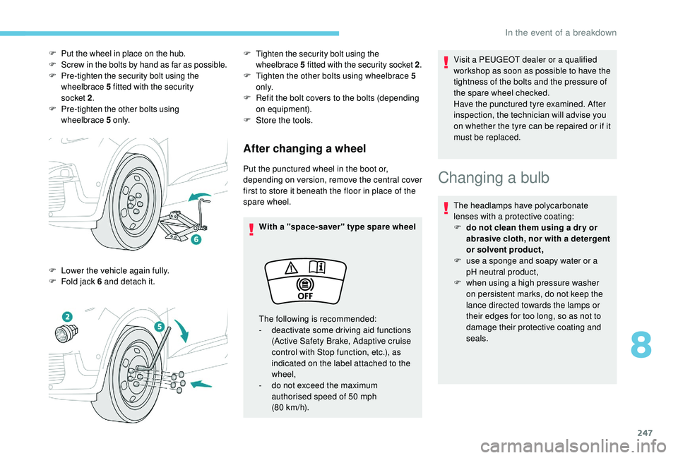
F
P
ut the wheel in place on the hub.
F
S
crew in the bolts by hand as far as possible.
F
P
re-tighten the security bolt using the
wheelbrace 5 fitted with the security
socket
2 .
F P
re-tighten the other bolts using
wheelbrace
5 o
n l y.
F
L
ower the vehicle again fully.
F
F
old jack 6 and detach it.
F Tighten the security bolt using the wheelbrace 5 fitted with the security socket 2 .
F Tighten the other bolts using wheelbrace 5
o n l y.
F
R
efit the bolt covers to the bolts (depending
on equipment).
F
S
tore the tools.
Changing a bulb
The headlamps have polycarbonate
lenses with a protective coating:
F
d
o not clean them using a dr y or
abrasive cloth, nor with a detergent
or solvent product,
F
u
se a sponge and soapy water or a
pH neutral product,
F
w
hen using a high pressure washer
on persistent marks, do not keep the
lance directed towards the lamps or
their edges for too long, so as not to
damage their protective coating and
seals.
8
In the event of a breakdown
Page 257 of 360
255
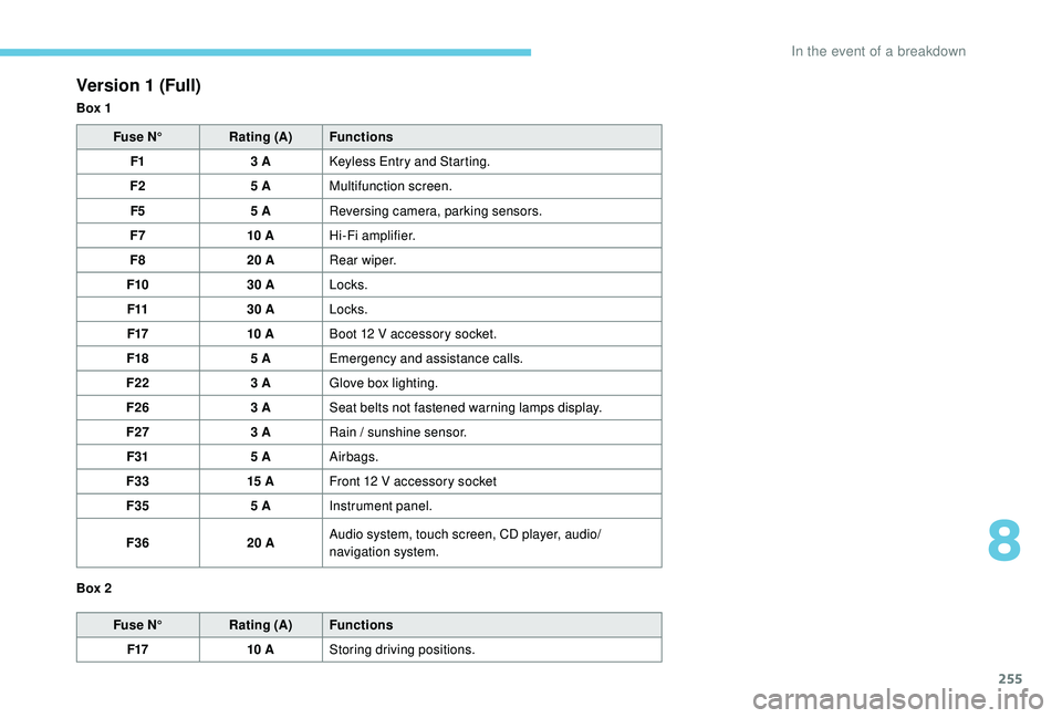
Version 1 (Full)
Box 1Fuse N° Rating (A) Functions
F1 3
A
K
eyless Entry and Starting.
F2 5
AMultifunction screen.
F5 5
AReversing camera, parking sensors.
F7 10
AHi-Fi amplifier.
F8 20
ARear wiper.
F10 30
ALocks.
F11 30
ALocks.
F17 10
ABoot 12
V accessory socket.
F18 5
AEmergency and assistance calls.
F22 3
AGlove box lighting.
F26 3
ASeat belts not fastened warning lamps display.
F27 3
ARain / sunshine sensor.
F31 5
AAirbags.
F33 15
AFront 12
V accessory socket
F35 5
AInstrument panel.
F36 20
AAudio system, touch screen, CD player, audio/
navigation system.
Fuse N° Rating (A) Functions
F17 10
AStoring driving positions.
Box 2
8
In the event of a breakdown