2018 PEUGEOT 3008 ECU
[x] Cancel search: ECUPage 148 of 360
146
Locations for i-Size child
seats
i-Size child seats have two latches that engage
on the two rings A.
i-Size child seats also have:
-
e
ither an upper strap that is attached to
ring
B,
-
o
r a support leg resting on the vehicle floor,
compatible with the approved i-Size seat,
the role of which is to prevent the child seat
from tipping for ward in the event of a collision.
For more information on ISOFIX mountings ,
refer to the associated section.
I UF:
seat suitable for installing an I sofix
U niversal seat, " For ward facing",
secured using the upper strap.
IL: seat suitable for installing an I sofix
S emi- Universal seat which is either:
-
"
rear ward facing" fitted with an
upper strap or a support leg,
-
"
for ward facing" fitted with a
support leg,
-
a c
ot fitted with an upper strap or
a support leg.
(a) Refer to the current legislation in your
country before installing a child at this
seating position.
(b) The installation of a cot on this seat
may prevent the use of one or more of
the other seats in this row.
For securing the upper strap using the ISOFIX
mountings
, refer to the corresponding section.
X: seat is not suitable for the installation
of an ISOFIX seat or cot of the weight
group indicated.
Safety
Page 150 of 360
148
Advice
The incorrect installation of a child seat in a
vehicle compromises the child's protection
in the event of an accident.
Ensure that there is no seat belt or seat
belt buckle under the child seat, as this
could destabilise it.
Remember to fasten the seat belts or the
child seat harnesses keeping the slack
relative to the child's body to a minimum,
even for short journeys.
When installing a child seat using the seat
belt, ensure that the seat belt is tightened
correctly on the child seat and that it
secures the child seat firmly on the seat
of your vehicle. If your passenger seat is
adjustable, move it forwards if necessary.
At rear seating positions, always leave
sufficient space between the front seat
and:
-
a r
ear ward facing child seat,
-
t
he child's feet for a child seat fitted
forward facing.
To do this, move the front seat for wards
and, if necessary, move its backrest into
the upright position.
For optimal installation of the forward
facing child seat, verify that its backrest is
as close as possible to the backrest of the
vehicle seat, if possible in contact with it. The head restraint must be removed before
installing a child seat with a backrest on a
passenger seat.
Ensure that the head restraint is stored or
attached securely to prevent it from being
thrown around the vehicle in the event of
sharp braking. Refit the head restraint when
the child seat is removed.
Children in front
The legislation on carrying children on the
front passenger seat is specific to each
country. Refer to the legislation in force in
your country.
Deactivate the front passenger airbag when
a
rear ward facing child seat is installed on
the front passenger seat.
Otherwise, the child would risk being seriously
injured or killed if the airbag were deployed.
Installing a booster seat
The chest part of the seat belt must be
positioned on the child's shoulder without
touching the neck.
Ensure that the lap part of the seat belt
passes correctly over the child's thighs.
PEUGEOT recommends using a booster seat
with a backrest equipped with a belt guide at
shoulder level. As a safety precaution, do not leave:
-
a c hild or children alone and unattended in
a vehicle,
-
a c
hild or an animal in a vehicle which
is exposed to the sun, with the windows
closed,
-
t
he keys within reach of children inside the
vehicle.
To prevent accidental opening of the doors
and rear windows, use the child lock.
Take care not to open the rear windows by
more than one third.
To protect young children from the rays of the
sun, fit side blinds on the rear windows.
Safety
Page 190 of 360
188
The cruise control operates by day and
night, in fog or moderate rainfall.
However, it is strongly recommended
that you always keep a safe distance
from vehicles ahead, according to the
driving conditions, the weather and the
road surface.
Use the cruise control only where
the driving conditions allow running
at a constant speed and keeping an
adequate safety distance.
Do not activate the cruise control in an
urban area where pedestrians are likely
to cross the road, in heavy traffic, on
winding or steep roads, on slippery or
flooded roads, when there is snowfall,
if the front bumper or the windscreen
is damaged, or when the brake lamps
have failed.
In certain circumstances, it may not
be possible for the speed setting to be
maintained or even attained: loaded
vehicle, ascending a steep hill, etc.The system is not intended for the
following situations:
-
i
f the front end of the vehicle has
been modified (addition of long-range
headlamps, painting of the front
bumper),
-
d
riving on a racing circuit,
-
r
unning on a rolling road,
-
u
se of snow chains, non-slip covers or
studded tyres.
The use of mats not approved by
PEUGEOT may inter fere with the
operation of the cruise control.
To avoid any risk of jamming of the pedals:
-
e
nsure that the mat is secured
c o r r e c t l y,
-
d
o not fit one mat on top of another.The camera may be disrupted or not
work in the following situations:
-
p
oor visibility (inadequate street
lighting, falling snow, heavy rain,
dense fog, etc.),
-
d
azzle (headlamps of an oncoming
vehicle, low sun, reflections on
a damp road, leaving a tunnel,
alternating shade and light, etc.),
-
c
amera or radar obstructed (mud,
frost, snow, condensation, etc.).
In these situations, detection
performance may be reduced.
Operation of the radar, located in the
front bumper, may be impaired by the
accumulation of dirt (dust, mud, etc.)
or in certain weather conditions (snow,
f r o s t , e t c .) .
Clean the front bumper regularly.
Clean the windscreen regularly,
particularly the area in front of the
detection camera.
Do not allow snow to accumulate on
the bonnet or roof of the vehicle, as this
could obscure the camera.
Driving
Page 222 of 360
220
Towbar with quickly
detachable towball
No tools are required to install or remove the
towball on this genuine towbar system.
Presentation
Trailers with LED lamps are not
compatible with the wiring harness of this
device.To know the Technical data
, and, in
particular, the towable weights for your
vehicle, refer to the corresponding
section.
To ensure complete safety while driving
with a Towbar system , refer to the
corresponding section.
Before each use
Check that the towball is correctly fitted,
verifying the follow points:
-
t
he green mark on the locking wheel
is in line with the green mark on the
towball,
-
t
he locking wheel is in contact with the
towball (position A ),
-
t
he security key lock is on and the key
removed; the locking wheel can no
longer be operated,
- t he towball must not be able to move
in its carrier; test by shaking it with
your hand.
If the towball is not locked, the trailer can
detach
– accident risk!
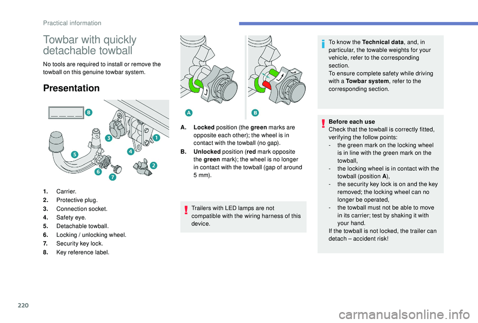
1.
Carrier.
2. Protective plug.
3. Connection socket.
4. Safety eye.
5. Detachable towball.
6. Locking / unlocking wheel.
7. Security key lock.
8. Key reference label. A.
Locked position (the green marks are
opposite each other); the wheel is in
contact with the towball (no gap).
B. Unlocked position (red mark opposite
the green mark); the wheel is no longer
in contact with the towball (gap of around
5
m m).
Practical information
Page 228 of 360
226
Fitting directly to the roof
Recommendations
Distribute the load uniformly, taking care
to avoid overloading one of the sides.
Arrange the heaviest part of the load as
close as possible to the roof.
Lash the load securely.
Drive gently: the vehicle will be more
susceptible to the effects of side winds
and the stability of the vehicle may be
affected.
On a long journey, check the security of
the load at every stop.
Remove the roof bars once they are no
longer needed.Sunroof
Check that the load does not pass below
the roof bars so that it does not impede
the movements of the sunroof.
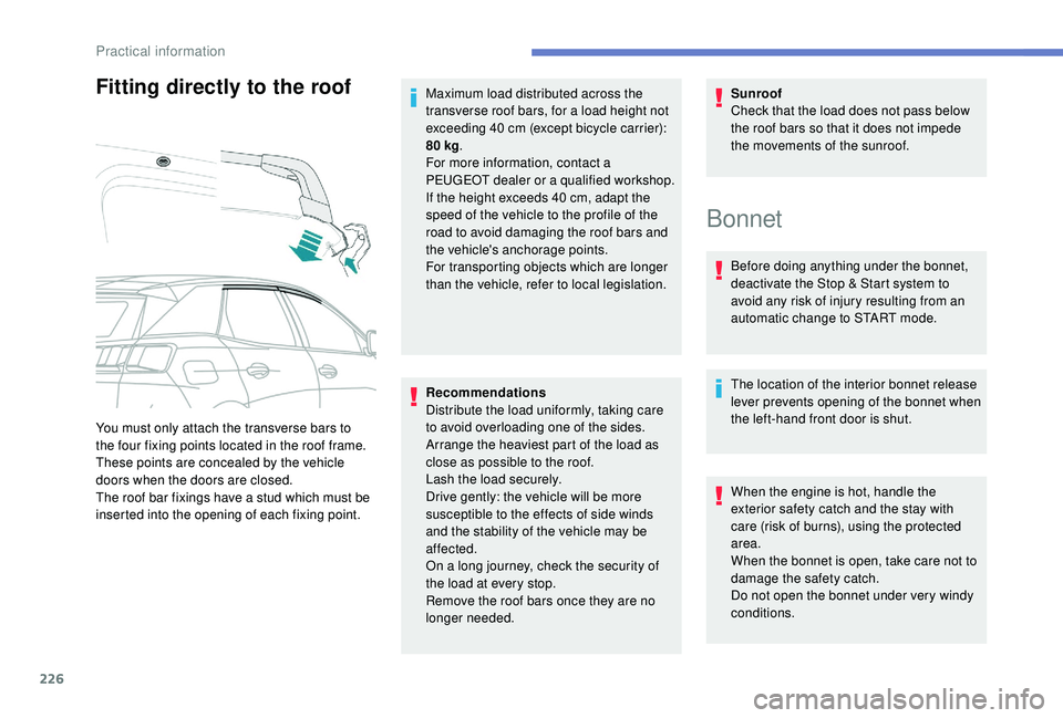
You must only attach the transverse bars to
the four fixing points located in the roof frame.
These points are concealed by the vehicle
doors when the doors are closed.
The roof bar fixings have a stud which must be
inserted into the opening of each fixing point. Maximum load distributed across the
transverse roof bars, for a load height not
exceeding 40
cm (except bicycle carrier):
80 kg
.
For more information, contact a
PEUGEOT dealer or a qualified workshop.
If the height exceeds 40 cm, adapt the
speed of the vehicle to the profile of the
road to avoid damaging the roof bars and
the vehicle's anchorage points.
For transporting objects which are longer
than the vehicle, refer to local legislation.
Bonnet
Before doing anything under the bonnet,
deactivate the Stop & Start system to
avoid any risk of injury resulting from an
automatic change to START mode.
The location of the interior bonnet release
lever prevents opening of the bonnet when
the left-hand front door is shut.
When the engine is hot, handle the
exterior safety catch and the stay with
care (risk of burns), using the protected
area.
When the bonnet is open, take care not to
damage the safety catch.
Do not open the bonnet under very windy
conditions.
Practical information
Page 241 of 360
239
All of these tools are specific to your
vehicle and may vary depending on
equipment.
Do not use them for any other purposes.
The jack must only be used to change a
wheel with a damaged or punctured tyre.
Do not use any jack other than the one
supplied with this vehicle.
If the vehicle does not have its original
jack, contact a PEUGEOT dealer or a
qualified workshop to obtain the correct
jack for it.
The jack meets European standards,
as defined in the Machinery Directive
2006/42/CE.
The jack does not require any
maintenance.
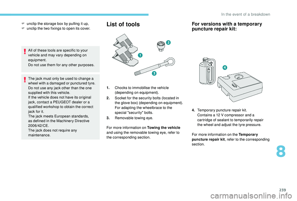
List of tools
1.Chocks to immobilise the vehicle
(depending on equipment).
2. Socket for the security bolts (located in
the glove box) (depending on equipment).
For adapting the wheelbrace to the
special "security" bolts.
3. Removable towing eye.
For more information on Towing the vehicle
and using the removable towing eye, refer to
the corresponding section.
For versions with a temporary
puncture repair kit:
For more information on the Temporary
puncture repair kit , refer to the corresponding
section.
F
u
nclip the storage box by pulling it up,
F
u
nclip the two fixings to open its cover.
4.Temporary puncture repair kit.
Contains a 12 V compressor and a
cartridge of sealant to temporarily repair
the wheel and adjust the tyre pressure.
8
In the event of a breakdown
Page 243 of 360
241
Avoid removing any foreign bodies which
have penetrated into the tyre.
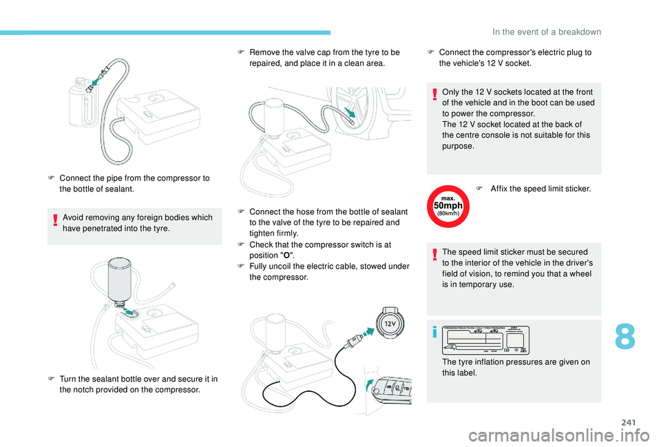
F
C
onnect the pipe from the compressor to
the bottle of sealant. F
R
emove the valve cap from the tyre to be
repaired, and place it in a clean area.
F
C
heck that the compressor switch is at
position " O".
F
F
ully uncoil the electric cable, stowed under
the compressor. Only the 12
V sockets located at the front
of the vehicle and in the boot can be used
to power the compressor.
The 12 V socket located at the back of
the centre console is not suitable for this
purpose.
F
A
ffix the speed limit sticker.
The speed limit sticker must be secured
to the interior of the vehicle in the driver's
field of vision, to remind you that a wheel
is in temporary use.
F
T
urn the sealant bottle over and secure it in
the notch provided on the compressor. F
C onnect the hose from the bottle of sealant
to the valve of the tyre to be repaired and
tighten firmly. F
C
onnect the compressor's electric plug to
the vehicle's 12 V socket.
The tyre inflation pressures are given on
this label.
8
In the event of a breakdown
Page 247 of 360
245
Parking the vehicle
Immobilise the vehicle where it does not
block traffic: the ground must be level,
stable and non-slippery.
Apply the parking brake, unless it is
programmed to be in automatic mode;
switch off the ignition and with a manual
gearbox, engage first gear so as to lock
the wheels.
Apply the parking brake, unless it is
programmed to be in automatic mode;
switch off the ignition and with an
automatic gearbox, select mode P so as
to lock the wheels.
Check that the parking brake warning
lamps in the instrument panel are on
fixed (not
flashing).
The occupants must get out of the
vehicle and wait where they are safe.
If necessary, place a chock under the
wheel diagonally opposite the wheel to
be changed.
Never go underneath a vehicle raised
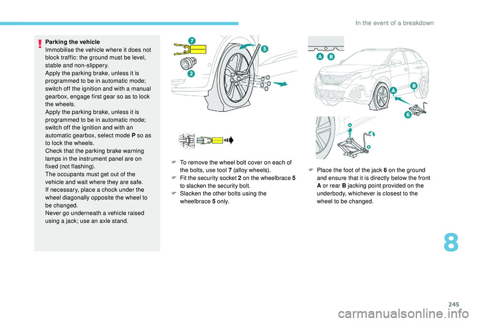
using a jack; use an axle stand. F
T
o remove the wheel bolt cover on each of
the bolts, use tool 7 (alloy wheels).
F
F
it the security socket 2 on the wheelbrace
5
to slacken the security bolt.
F
S
lacken the other bolts using the
wheelbrace 5 o n l y. F
P
lace the foot of the jack 6 on the ground
and ensure that it is directly below the front
A or rear B jacking point provided on the
underbody, whichever is closest to the
wheel to be changed.
8
In the event of a breakdown