2018 NISSAN ROGUE SPORT instrument panel
[x] Cancel search: instrument panelPage 300 of 512
start the engine.
.The cargo room area is not included in
the operating range but the Intelligent
Key may function.
. If the Intelligent Key is placed on the
instrument panel, inside the glove box
or door pocket, the Intelligent Key may
not function.
. If the Intelligent Key is placed near the
door or window outside the vehicle,
the Intelligent Key may function.
PUSH-BUTTON IGNITION SWITCH
OPERATION
CAUTION
.Do not leave the vehicle for ex-
tended periods of time when the
ignition switch is in the ON posi-
tion and the engine is not run-
ning. This can discharge the
battery.
. Use electrical accessories with
the engine running to avoid dis-
charging the vehicle battery. If
you must use accessories while
the engine is not running, do not
use them for extended periods of
time and do not use multiple
electrical accessories at the same time.
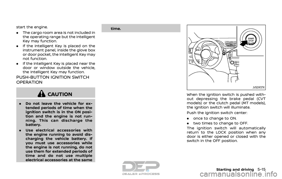
JVS0937X
When the ignition switch is pushed with-
out depressing the brake pedal (CVT
models) or the clutch pedal (MT models),
the ignition switch will illuminate.
Push the ignition switch center:
.
once to change to ON.
. two times to change to OFF.
The ignition switch will automatically
return to the LOCK position when any
door is either opened or closed with the
switch in the OFF position.
Starting and driving5-15
Page 321 of 512
5-36Starting and driving
— When a sudden change inbrightness occurs. (For exam-
ple, when the vehicle enters or
exits a tunnel or under a
bridge.)
SYSTEM TEMPORARILY UNAVAIL-
ABLE
Condition A:
If the vehicle is parked in direct sunlight
under high temperature conditions (over
approximately 104°F (40°C)) and then
started, the LDW system may be deacti-
vated automatically, the LDW indicator
will flash and the following message will
appear in the vehicle information display.
- “Unavailable: High Cabin Temperature”
When the interior temperature is reduced,
the LDW system will resume operating
automatically and the LDW indicator will
stop flashing.
Condition B:
The warning function of the LDW system
is not designed to work under the follow-
ing conditions:
. When you operate the lane change
signal and change traveling lanes in
the direction of the signal. (The LDW
system will become operable again
approximately 2 seconds after the lane change signal is turned off.)
. When the vehicle speed lowers to less
than approximately 37 MPH (60 km/h).
Action to take:
After the above conditions have finished
and the necessary operating conditions
are satisfied, the LDW system will resume.
SYSTEM MALFUNCTION
If the LDW system malfunctions, it will
cancel automatically and “Malfunction”
will appear in the vehicle information
display. If “Malfunction” appears in the
vehicle information display, pull off the
road to a safe location and stop the
vehicle. Place the ignition switch in the
OFF position and restart the engine. If
“Malfunction” continues to appear in the
vehicle information display, have the
system checked. It is recommended that
you visit a NISSAN dealer for this service.
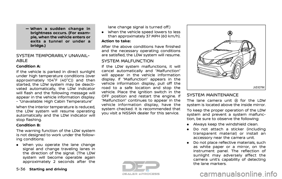
JVS1079X
SYSTEM MAINTENANCE
The lane camera unitfor the LDW
system is located above the inside mirror.
To keep the proper operation of the LDW
system and prevent a system malfunc-
tion, be sure to observe the following:
. Always keep the windshield clean.
. Do not attach a sticker (including
transparent material) or install an
accessory near the camera unit.
. Do not place reflective materials, such
as white paper or a mirror, on the
instrument panel. The reflection of
sunlight may adversely affect the
camera unit’s capability of detecting
the lane markers.
Page 324 of 512
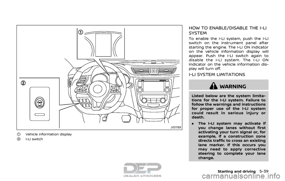
JVS1118X
Vehicle information displayI-LI switch
HOW TO ENABLE/DISABLE THE I-LI
SYSTEM
To enable the I-LI system, push the I-LI
switch on the instrument panel after
starting the engine. The I-LI ON indicator
on the vehicle information display will
appear. Push the I-LI switch again to
disable the I-LI system. The I-LI ON
indicator on the vehicle information dis-
play will turn off.
I-LI SYSTEM LIMITATIONS
WARNING
Listed below are the system limita-
tions for the I-LI system. Failure to
follow the warnings and instructions
for proper use of the I-LI system
could result in serious injury or
death.
.The I-LI system may activate if
you change lanes without first
activating your turn signal or, for
example, if a construction zone
directs traffic to cross an existing
lane marker. If this occurs you
may need to apply corrective
steering to complete your lane
change.
Starting and driving5-39
Page 327 of 512
5-42Starting and driving
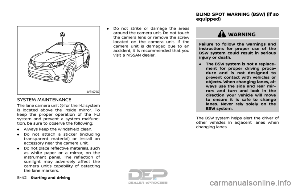
JVS1079X
SYSTEM MAINTENANCE
The lane camera unitfor the I-LI system
is located above the inside mirror. To
keep the proper operation of the I-LI
system and prevent a system malfunc-
tion, be sure to observe the following:
. Always keep the windshield clean.
. Do not attach a sticker (including
transparent material) or install an
accessory near the camera unit.
. Do not place reflective materials, such
as white paper or a mirror, on the
instrument panel. The reflection of
sunlight may adversely affect the
camera unit’s capability of detecting
the lane markers. .
Do not strike or damage the areas
around the camera unit. Do not touch
the camera lens or remove the screw
located on the camera unit. If the
camera unit is damaged due to an
accident, it is recommended that you
visit a NISSAN dealer.
WARNING
Failure to follow the warnings and
instructions for proper use of the
BSW system could result in serious
injury or death.
.The BSW system is not a replace-
ment for proper driving proce-
dure and is not designed to
prevent contact with vehicles or
objects. When changing lanes, al-
ways use the side and rear mir-
rors and turn and look in the
direction your vehicle will move
to ensure it is safe to change
lanes. Never rely solely on the
BSW system.
The BSW system helps alert the driver of
other vehicles in adjacent lanes when
changing lanes.
BLIND SPOT WARNING (BSW) (if so
equipped)
Page 383 of 512

5-98Starting and driving
JVS1042X
SYSTEM MAINTENANCE
The radar sensoris located on the front
of the vehicle. The camerais located on
the upper side of the windshield.
To keep the AEB with pedestrian detec-
tion system operating properly, be sure to
observe the following:
. Always keep the sensor area on the
front of the vehicle and windshield
clean.
. Do not strike or damage the areas
around the sensors (ex. bumper, wind-
shield).
. Do not cover or attach stickers or
similar objects on the front of the
vehicle near the sensor area. This could cause failure or malfunction.
. Do not attach metallic objects near
the radar sensor area (brush guard,
etc.). This could cause failure or mal-
function.
. Do not place reflective materials, such
as white paper or a mirror, on the
instrument panel. The reflection of
sunlight may adversely affect the
camera unit’s detection capability.
. Do not alter, remove or paint the front
of the vehicle near the sensor area.
Before customizing or restoring the
sensor area, it is recommended that
you visit a NISSAN dealer.
Radio frequency statement
For USA
FCC : OAYSRR3B
This device complies with part 15 of the
FCC Rules. Operation is subject to the
following two conditions:
(1) This device may not cause harmful
interference, and (2) this device must
accept any interference received, in-
cluding interference that may cause
undesired operation.
FCC Warning
Changes or modifications not expressly
approved by the party responsible for
compliance could void the user’s
authority to operate the equipment For Canada
Applicable law: Canada 310
This device complies with Industry Ca-
nada licence-exempt RSS standard(s).
Operation is subject to the following
two conditions: (1) this device may not
cause interference, and (2) this device
must accept any interference, including
interference that may cause undesired
operation of the device.
Frequency bands: 24.05 – 24.25GHz
Output power: less than 20 milliwatts
Page 387 of 512
5-102Starting and driving
mended that you visit a NISSAN
dealer for this service.
. If the “AWD Error” warning ap-
pears while driving, there may be
a malfunction in the AWD system.
Reduce the vehicle speed and
have your vehicle checked as
soon as possible. It is recom-
mended that you visit a NISSAN
dealer for this service.
. Never drive on dry, hard surface
roads in the LOCK mode, as this
will overload the powertrain and
may cause a serious malfunction.
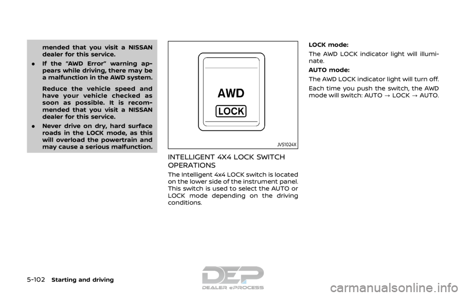
JVS1024X
INTELLIGENT 4X4 LOCK SWITCH
OPERATIONS
The Intelligent 4x4 LOCK switch is located
on the lower side of the instrument panel.
This switch is used to select the AUTO or
LOCK mode depending on the driving
conditions. LOCK mode:
The AWD LOCK indicator light will illumi-
nate.
AUTO mode:
The AWD LOCK indicator light will turn off.
Each time you push the switch, the AWD
mode will switch: AUTO
?LOCK ?AUTO.
Page 393 of 512

5-108Starting and driving
tion, it switches the ABS off and illumi-
nates the ABS warning light on the
instrument panel. The brake system then
operates normally, but without anti-lock
assistance.
If the ABS warning light illuminates during
the self-test or while driving, have the
vehicle checked. It is recommended you
visit a NISSAN dealer for this service.
Normal operation
The ABS operates at speeds above 3 to 6
MPH (5 to 10 km/h). The speed varies
according to road conditions.
When the ABS senses that one or more
wheels are close to locking up, the
actuator rapidly applies and releases
hydraulic pressure. This action is similar
to pumping the brakes very quickly. You
may feel a pulsation in the brake pedal
and hear a noise from under the hood or
feel a vibration from the actuator when it
is operating. This is normal and indicates
that the ABS is operating properly. How-
ever, the pulsation may indicate that road
conditions are hazardous and extra care
is required while driving.The Vehicle Dynamic Control (VDC) sys-
tem uses various sensors to monitor
driver inputs and vehicle motion. Under
certain driving conditions, the VDC sys-
tem helps to perform the following func-
tions.
.
Controls brake pressure to reduce
wheel slip on one slipping drive wheel
so power is transferred to a non
slipping drive wheel on the same axle.
. Controls brake pressure and engine
output to reduce drive wheel slip
based on vehicle speed (traction con-
trol function).
. Controls brake pressure at individual
wheels and engine output to help the
driver maintain control of the vehicle
in the following conditions:
— understeer (vehicle tends to not
follow the steered path despite
increased steering input)
— oversteer (vehicle tends to spin due to certain road or driving condi-
tions).
The VDC system can help the driver to
maintain control of the vehicle, but it
cannot prevent loss of vehicle control in
all driving situations.
When the VDC system operates, the VDC
warning light
in the instrument panel
flashes so note the following: .
The road may be slippery or the
system may determine some action
is required to help keep the vehicle on
the steered path.
. You may feel a pulsation in the brake
pedal and hear a noise or vibration
from under the hood. This is normal
and indicates that the VDC system is
working properly.
. Adjust your speed and driving to the
road conditions.
If a malfunction occurs in the system, the
VDC warning light
illuminates in the
instrument panel. The VDC system auto-
matically turns off.
The VDC OFF switch is used to turn off the
VDC system. The VDC off indicator
illuminates to indicate the VDC system is
off. When the VDC switch is used to turn
off the system, the VDC system still
operates to prevent one drive wheel from
slipping by transferring power to a non
slipping drive wheel. The VDC warning
light
flashes if this occurs. All other
VDC functions are off, and the VDC
warning light
will not flash. The VDC
system is automatically reset to on when
the ignition switch is placed in the off
position then back to the on position.
See “Vehicle Dynamic Control (VDC) warn-
ing light” (P.2-15) and “Vehicle Dynamic
Control (VDC) off indicator light” (P.2-17).
VEHICLE DYNAMIC CONTROL (VDC) SYSTEM
Page 504 of 512
11 Index
A
ABS (Anti-lock Braking System) .................... 5-107
Active Ride Control ................................................. 5-112
Advanced air bag system ..................................... 1-46
Air bag systemAdvanced air bag system .............................. 1-46
Front passenger air bag and
status light................................................................. 1-48
Front-seat mounted side-impact
supplemental air bag system..................... 1-54
Roof-mounted curtain side-impact
supplemental air bag system..................... 1-54
Air bag warning labels ............................................ 1-56
Air bag warning light................................. 1-57, 2-15
Air cleaner housing filter ....................................... 8-15
Air conditioner Air conditioner operation............................... 4-30
Air conditioner service...................................... 4-37
Air conditioner specification label....... 10-10
Air conditioning system refrigerant
and lubricant
recommendations ................................ 4-37, 10-6
Alarm, How to stop alarm (see vehicle
security system)............................................................ 2-38
Alcohol, drugs and driving ................................... 5-10
Antenna........................................................................\
....... 4-77
Anti-lock Braking System (ABS) .................... 5-107
Anti-lock braking system (ABS)
warning light ................................................................... 2-10
Appearance care Exterior appearance care ................................. 7-2
Interior appearance care................................... 7-4
Application download.............................................. 4-78
Armrest ........................................................................\
............ 1-6
Audible reminders....................................................... 2-17 Audio operation precautions ............................. 4-38
Audio system .................................................................. 4-38
Steering wheel audio controls................... 4-75
Automatic Door locks...................................................................... 3-7
Automatic air conditioner .................................... 4-35
Automatic Emergency Braking (AEB) .......... 5-82
Automatic Emergency Braking (AEB)
system warning light................................................ 2-12
Automatic Emergency Braking (AEB) with
pedestrian detection system ............................. 5-89
AUX (Auxiliary) input jack....................................... 4-75
Average speed ............................................................... 2-34
Avoiding collision and rollover.............................. 5-8
B
Battery........................................................................\
.......... 8-11 Battery replacement, Intelligent Key ..... 8-23
Battery replacement, Key fob..................... 8-21
Battery saver system......................................... 2-47
Variable voltage control system .............. 8-13
Before starting the engine................................... 5-17
Blind Spot Warning (BSW) ..................................... 5-42
Bluetooth® Hands-Free
Phone System ................................................. 4-83, 4-93
Booster seats.................................................................. 1-36
Brake Anti-lock Braking System (ABS) ............ 5-107
Brake and clutch fluid ......................................... 8-9
Brake system ....................................................... 5-106
Electronic parking brake system
warning light ............................................................ 2-12
Parking brake .......................................................... 5-27 Press Brake Pedal warning
(for electronic parking brake
equipped models) ................................................ 2-32
Warning light............................................................ 2-11
Break-in schedule ....................................................... 5-99
Brightness control Instrument panel ..................................................... 2-9
Bulb check/instrument panel............................ 2-10
Bulb replacement ........................................................ 8-25
C
Capacities and
recommended fluids/lubricants...................... 10-2
Car phone or CB radio ............................................ 4-83
Card holder....................................................................... 2-57
Cargo area ........................................................................\
2-55
Catalytic converter, Three way catalyst ....... 5-4
CD/USB memory care and cleaning............ 4-77
Chassis and body maintenance...................... 9-11
Chassis control............................................ 2-35, 5-110
Child restraints .............................................................. 1-20 Booster seats........................................................... 1-36
LATCH system ......................................................... 1-22
Precautions on child restraints................. 1-20
Child safety....................................................................... 1-17
Child safety rear door lock ...................................... 3-7
Chimes, Audible reminders.................................. 2-17
Circuit breaker, Fusible link ................................. 8-19
Cleaning exterior and interior ................... 7-2, 7-4
Clock ........................................................................\
.............. 2-36
Clutch fluid........................................................................\
.... 8-9
Cockpit ........................................................................\
............. 2-3
Cold weather driving ............................................. 5-113
Console box ..................................................................... 2-56
Console light ................................................................... 2-66