Page 301 of 426
A. Tire stoppers
B. Flat Tire
Blocking wheels
Place tire stoppers, supplied in tool kit, at
both the front and back of the wheel diago-
nally opposite the flat tire to prevent the
vehicle from moving when it is jacked up.
WARNING
Be sure to block the wheel as the vehicle
may move and result in personal injury.
Getting the spare tire and tools
The jack and tool kit are located behind the
rear passenger side access cover. To re-
move the jack and tool kit perform the fol-
lowing:1. Remove the access cover
�1. 2. To easily access removing the jack, first
remove the tool kit by unscrewing the
retainer
�2counterclockwise.
3. Remove the tool bag.
LCE2142LCE2032LCE2030
6-4In case of emergency
Page 302 of 426

4. To release the jack, lower the jack byturning the jack lever
�3counterclock-
wise until the lock rod
�4canbelow-
ered.
5. Lif t the jack to remove. 6. Assemble the extension and the
J-shaped end tool together before in-
serting them into the oval-shaped
opening above the middle of the rear
step bumper. Pass the J-shaped end of
the jack rod through the opening and
direct it toward the spare tire winch,
located directly above the spare tire.
CAUTION
Do not insert the jack rod straight as it is
designed to be inserted at an angle as
shown. 7. Fit the square end of the jack rod into
the square hole of the wheel nut
wrench to form a handle.
8. Seat the J-shaped end of the jack rod into the opening of the tire winch. Apply
pressure to keep the jack rod engaged
in the spare tire winch and turn the jack
rod counterclockwise to lower the
spare tire.
9. Once the spare tire is completely low- ered, reach under the vehicle, remove
the retainer chain, and carefully slide
the tire from under the rear of the ve-
hicle. Do not remove the rubber spacer.
LCE2031LCE2033LCE2034
In case of emergency6-5
Page 303 of 426
10. To reinstall the wheel, insert the tirechain through the wheel. Be sure the
rubber spacer is centered on the wheel
before lif ting. Use the assembled jack
rod and slowly rotate the winch clock-
wise to raise the wheel to the vehicle.
NOTE:
Inspect the spacer every six years and
replace as necessary. Contact a NISSAN
dealer for replacement parts if neces-
sary.
CAUTION
∙ Be sure to center the spare tire sus- pending plate on the wheel and then
lif t the spare tire.
∙ Failure to use the spacer may allow the chain to get stuck on the wheel
nut holes.
Removing bolt-on wheel caps
CAUTION
Do not use your hands to pry off wheel
caps or wheel covers. Doing so could
result in personal injury.
The wheel cap�1is only attached with the
wheel nuts and is separate from the wheel
�2.
To remove the wheel cap, remove the
wheel nuts af ter the jack is securely sup-
porting the vehicle and the tire clears the
ground.
LCE2017LCE2367
6-6In case of emergency
Page 304 of 426

For additional information, refer to “Jacking
up vehicle and removing the damaged tire”
in this section.
Take care not to scratch the wheel cap or
wheel surface.
Jacking up vehicle and removing
the damaged tire
WARNING
∙ Never get under the vehicle while it issupported only by the jack. If it is nec-
essary to work under the vehicle, sup-
port it with safety stands.
∙ Use only the jack provided with your vehicle to lif t the vehicle. Do not use
the jack provided with your vehicle on
other vehicles. The jack is designed
for lif ting only your vehicle during a
tire change.
∙ Use the correct jack-up points. Never use any other part of the vehicle for
jack support.
∙ Never jack up the vehicle more than necessary.
∙ Never use blocks on or under the jack. ∙ Do not start or run the engine while
the vehicle is on the jack. It may cause
the vehicle to move.
∙ Do not allow passengers to stay in the vehicle while it is on the jack.
∙ Never run the engine with a wheel(s) off the ground. It may cause the ve-
hicle to move.
Always refer to the illustration for the cor-
rect placement and jack-up points for your
specific vehicle model and jack type.
Carefully read the caution label attached
to the jack body and the following in-
structions. 1. Loosen each wheel nut one or two turns by turning counterclockwise with
the wheel nut wrench. Do not remove
the wheel nuts until the tire is off the
ground.
In case of emergency6-7
Page 330 of 426
CAUTION
Oil level should be checked regularly.
Operating the engine with an insuffi-
cient amount of oil can damage the en-
gine, and such damage is not covered
by warranty.
CHANGING ENGINE OIL
1. Park the vehicle on a level surface andapply the parking brake. 2. Start the engine and let it idle until it
reaches operating temperature, then
turn it off.
3. Remove the oil filler cap
�Aby turning it
counterclockwise.
VQ40DE engineLDI2595
VK56VD engine
LDI3068
Do-it-yourself8-9
Page 331 of 426

4. Place a large drain pan under the drainplug
�B.
5. Remove the drain plug
�Bwith a
wrench by turning it counterclockwise
and completely drain the oil.
If the oil filter is to be changed, remove
and replace it at this time. For addi-
tional information, refer to “Changing
engine oil filter” in this section.
∙ Waste oil must be disposed of prop-
erly.
∙ Check your local regulations.
WARNING
∙ Prolonged and repeated contact with
used engine oil may cause skin
cancer.
∙ Try to avoid direct skin contact with used oil. If skin contact is made, wash
thoroughly with soap or hand cleaner
as soon as possible.
∙ Keep used engine oil out of reach of children.
CAUTION
Be careful not to burn yourself. The en-
gine oil may be hot.
6. Clean and reinstall the drain plug and a new washer. Securely tighten the drain
plug with a wrench. Do not use exces-
sive force.
Drain plug tightening torque: 25 f t-lb (34 N·m)
7. Refill engine with recommended oil through the oil filler opening, then install
the oil filler cap securely.
For additional information, refer to
“Recommended fluids/lubricants and
capacities” in the “Technical and con-
sumer information” section of this
manual for drain and refill capacity.
The drain and refill capacity depends
on the oil temperature and drain time.
Use these specifications for reference
only. Always use the dipstick to deter-
mine when the proper amount of oil is
in the engine.
8. Start the engine. Check for leakage around the drain plug and oil filter. Cor-
rect as required. 9. Turn the engine off and wait more than
10 minutes. Check the oil level with the
dipstick. Add engine oil if necessary.
8-10Do-it-yourself
Page 332 of 426
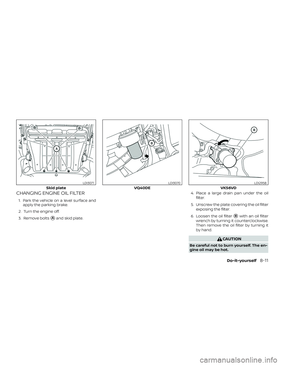
CHANGING ENGINE OIL FILTER
1. Park the vehicle on a level surface andapply the parking brake.
2. Turn the engine off.
3. Remove bolts
�Aand skid plate. 4. Place a large drain pan under the oil
filter.
5. Unscrew the plate covering the oil filter exposing the filter.
6. Loosen the oil filter�Bwith an oil filter
wrench by turning it counterclockwise.
Then remove the oil filter by turning it
by hand.
CAUTION
Be careful not to burn yourself. The en-
gine oil may be hot.
Skid plate
LDI3071
VQ40DE
LDI3070
VK56VD
LDI2958
Do-it-yourself8-11
Page 350 of 426

For additional information on fog light bulb
replacement, refer to the instructions out-
lined in this section.
Replacing the fog light bulb
CAUTION
∙ High pressure halog")
FOG LIGHTS (if so equipped)
For additional information on fog light bulb
replacement, refer to the instructions out-
lined in this section.
Replacing the fog light bulb
CAUTION
∙ High pressure halogen gas is sealedinside the halogen bulb. The bulb may
break if the glass envelope is
scratched or the bulb is dropped.
∙ When handling the bulb, do not touch the glass envelope.
∙ Use the same number and wattage as originally installed as shown in the
chart.
∙ Do not leave the bulb out of the fog light for a long period of time as dust,
moisture and smoke may enter the
fog light body and affect the perfor-
mance of the fog light. 1. Disconnect the negative (-) battery
cable.
2. The fog light is accessible in front of the front tire and behind the bumper.
3. Disconnect the bulb connector
�1.
4. Rotate the bulb counterclockwise and remove.
5. Remove by pulling it straight out of the fog light assembly. Do not shake or ro-
tate the bulb when removing it. Do not
touch the glass envelope.
6. Install in the reverse order of removal.
LDI2082
Do-it-yourself8-29