Page 197 of 460
Entry/Exit function
The automatic drive positioner system will
make the steering wheel move up auto-
matically when the driver’s door is opened
and the ignition switch is in the LOCK posi-
tion. This lets the driver get into and out of
the seat more easily. The steering wheel
moves back into position when the driver’s
door is closed and the ignition switch is
pushed.
For additional information, refer to “Auto-
matic drive positioner” in this section.1. To block glare from the front, swing
down�1the main sun visor.
2. To block glare from the side, remove the main sun visor from the center
mount and swing the visor to the side
�2.
3. To extend
�3the sun visor, slide in or
out as needed.
CAUTION
∙ Do not store the sun visor before re- turning the extension to its original
position.
∙ Do not pull the extension sun visor forcedly downward.
WPD0344
SUN VISORS
Pre-driving checks and adjustments3-35
Page 201 of 460

The automatic drive positioner system has
three features:∙ Memory storage function (key-link)
∙ Memory storage function (switch)
∙ Entry/exit function
Key-link, when enabled, automatically re-
tains the driver’s last seat, automatic steer-
ing wheel, and outside mirror positions for
that specific key when the ignition is turned
from ON to OFF.
Each memory switch button (1 or 2) on the
driver’s door can also store one additional
position which is independent of the key-
linked position.
MEMORY STORAGE FUNCTION
(key-link)
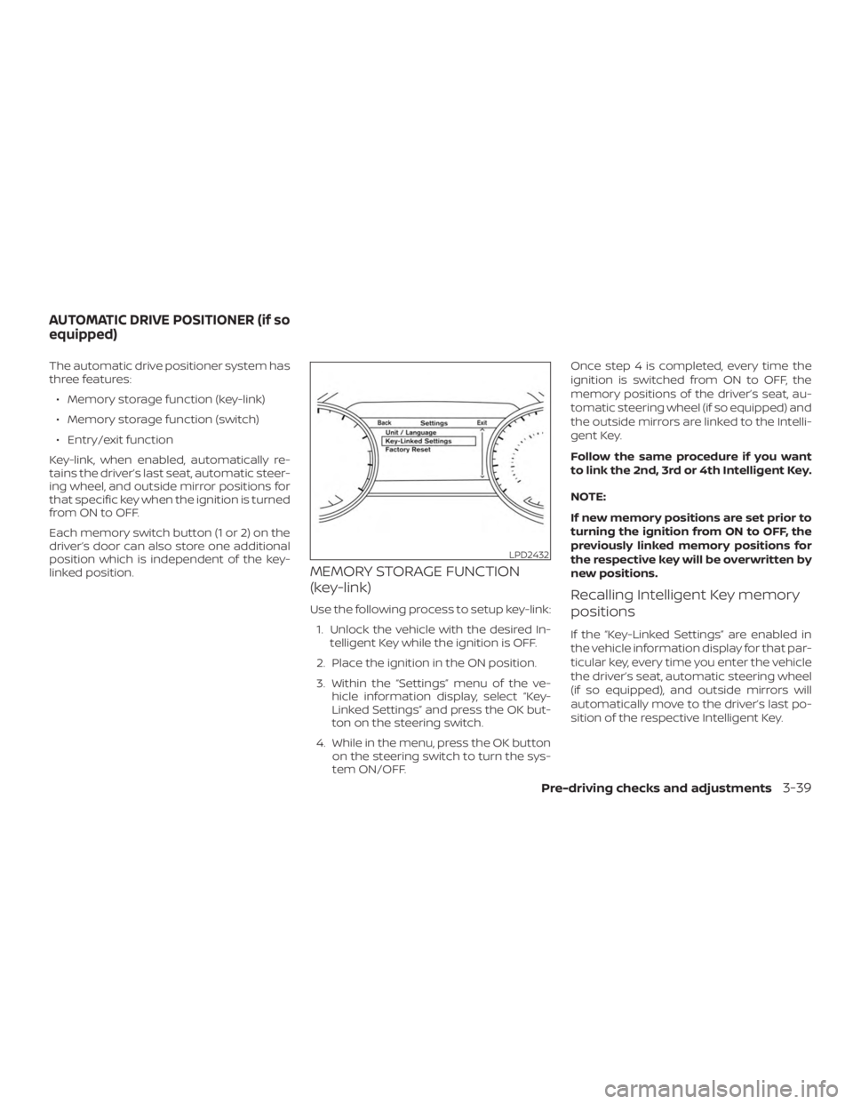
Use the following process to setup key-link: 1. Unlock the vehicle with the desired In- telligent Key while the ignition is OFF.
2. Place the ignition in the ON position.
3. Within the “Settings” menu of the ve- hicle information display, select “Key-
Linked Settings” and press the OK but-
ton on the steering switch.
4. While in the menu, press the OK button on the steering switch to turn the sys-
tem ON/OFF. Once step 4 is completed, every time the
ignition is switched from ON to OFF, the
memory positions of the driver’s seat, au-
tomatic steering wheel (if so equipped) and
the outside mirrors are linked to the Intelli-
gent Key.
Follow the same procedure if you want
to link the 2nd, 3rd or 4th Intelligent Key.
NOTE:
If new memory positions are set prior to
turning the ignition from ON to OFF, the
previously linked memory positions for
the respective key will be overwritten by
new positions.Recalling Intelligent Key memory
positions
If the “Key-Linked Settings” are enabled in
the vehicle information display for that par-
ticular key, every time you enter the vehicle
the driver’s seat, automatic steering wheel
(if so equipped), and outside mirrors will
automatically move to the driver’s last po-
sition of the respective Intelligent Key.
LPD2432
AUTOMATIC DRIVE POSITIONER (if so
equipped)
Pre-driving checks and adjustments3-39
Page 202 of 460

NOTE:
The key-linked memory positions can be
different from the positions stored in the
memory switch (1 or 2).
MEMORY STORAGE FUNCTION
(switch)
Use the following process to manually
store the two memory positions in the
switch:1. The vehicle should be stopped while setting the memory.
2. Adjust the driver’s seat, steering col- umn and outside mirrors to the desired
positions by manually operating each
adjusting switch. For additional infor-
mation, refer to “Seats” in the “Safety—
Seats, seat belts and supplemental re-
straint system” section of this manual and “Steering wheel” and “Outside mir-
rors” in this section.
3. Push the SET switch and, within 5 sec- onds, push the memory switch (1 or 2).
The indicator light for the pushed memory
switch will come on and stay on for ap-
proximately 5 seconds. The chime will
sound when the memory is stored.
NOTE:
If a new memory position is stored in the
same memory switch, the previous
memory position will be overwritten by
the new stored position.
Recalling switch memory
positions
To recall the manually stored positions,
press the memory switch (1 or 2). The driv-
er’s seat, outside mirrors and automatic
steering wheel (if so equipped) will move to
the positions stored to those buttons.
LPD2508
3-40Pre-driving checks and adjustments
Page 203 of 460

ENTRY/EXIT FUNCTION
This system is designed so that the driver’s
seat and steering column will automati-
cally move when the shif t lever is in the P
(Park) position. This allows the driver to
easily get in and out of the driver’s seat.
The driver’s seat will slide backward and
the steering wheel will move up:∙ When the driver’s door is opened and the ignition switch is in the OFF position.
∙ When the ignition switch is turned from ACC to OFF with the driver’s door open.
The driver’s seat and steering wheel will
return to the previous position: ∙ When the ignition switch is turned to ACC or ON while the shif t lever is in the P
(Park) position.
The entry/exit function can be adjusted or
canceled through the “Vehicle Settings” in
the vehicle information display by perform-
ing the following: ∙ Switch the Exit Seat Slide from ON to OFF.
∙ Switch the Exit Steering Up from ON to OFF.
Restarting the entry/exit function
If the battery cable is disconnected or if the
fuse opens, the stored memory positions
may be lost and some of the functions will
be restricted.
1. Drive the vehicle over 25 mph (40 km/h).
OR 2. Open and close the driver’s door more than two times with the ignition switch
in the OFF position.
The entry/exit function should now work
properly.
SYSTEM OPERATION
The automatic drive positioner system will
not work or will stop operating under the
following conditions: ∙ When the vehicle speed is above 4 mph (7km/h).
∙ When any of the memory switches are pushed while the automatic drive posi-
tioner is operating.
∙ When the switch for the driver’s seat and steering column is pushed while
the automatic drive positioner is oper-
ating. ∙ When the seat has already been moved
to the memorized position.
∙ When no seat position is stored in the memory switch.
∙ When the shif t lever is moved from P (Park) to any other position.
Pre-driving checks and adjustments3-41
Page 209 of 460

HOW TO READ THE DISPLAYED
LINES
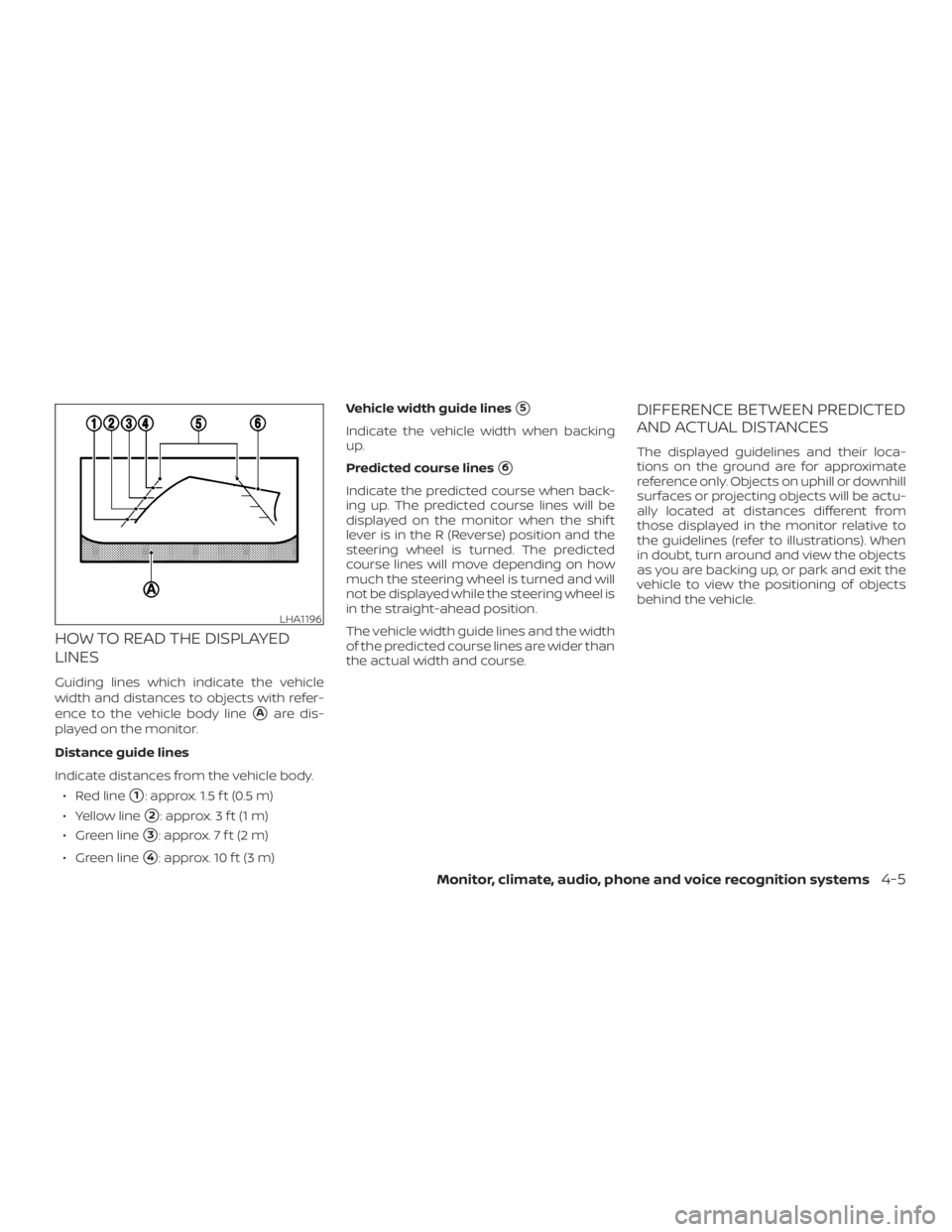
Guiding lines which indicate the vehicle
width and distances to objects with refer-
ence to the vehicle body line
�Aare dis-
played on the monitor.
Distance guide lines
Indicate distances from the vehicle body.
∙ Red line
�1: approx. 1.5 f t (0.5 m)
∙ Yellow line
�2: approx. 3 f t (1 m)
∙ Green line
�3: approx. 7 f t (2 m)
∙ Green line
�4: approx. 10 f t (3 m) Vehicle width guide lines
�5
Indicate the vehicle width when backing
up.
Predicted course lines
�6
Indicate the predicted course when back-
ing up. The predicted course lines will be
displayed on the monitor when the shif t
lever is in the R (Reverse) position and the
steering wheel is turned. The predicted
course lines will move depending on how
much the steering wheel is turned and will
not be displayed while the steering wheel is
in the straight-ahead position.
The vehicle width guide lines and the width
of the predicted course lines are wider than
the actual width and course.
DIFFERENCE BETWEEN PREDICTED
AND ACTUAL DISTANCES
The displayed guidelines and their loca-
tions on the ground are for approximate
reference only. Objects on uphill or downhill
surfaces or projecting objects will be actu-
ally located at distances different from
those displayed in the monitor relative to
the guidelines (refer to illustrations). When
in doubt, turn around and view the objects
as you are backing up, or park and exit the
vehicle to view the positioning of objects
behind the vehicle.
LHA1196
Monitor, climate, audio, phone and voice recognition systems4-5
Page 211 of 460

Backing up behind a projecting
object
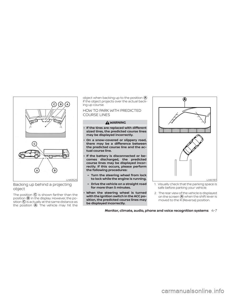
The position�Cis shown farther than the
position
�Bin the display. However, the po-
sition
�Cis actually at the same distance as
the position
�A. The vehicle may hit the object when backing up to the position
�A
if the object projects over the actual back-
ing up course.
HOW TO PARK WITH PREDICTED
COURSE LINES
WARNING
∙ If the tires are replaced with different
sized tires, the predicted course lines
may be displayed incorrectly.
∙ On a snow-covered or slippery road, there may be a difference between
the predicted course line and the ac-
tual course line.
∙ If the battery is disconnected or be- comes discharged, the predicted
course lines may be displayed incor-
rectly. If this occurs, please perform
the following procedures:
– Turn the steering wheel from lock to lock while the engine is running.
– Drive the vehicle on a straight road for more than 5 minutes.
∙ When the steering wheel is turned with the ignition switch in the ACC po-
sition, the predicted course lines may
be displayed incorrectly. 1. Visually check that the parking space is
safe before parking your vehicle.
2. The rear view of the vehicle is displayed on the screen
�Awhen the shif t lever is
moved to the R (Reverse) position.
LHA3525LHA1197
Monitor, climate, audio, phone and voice recognition systems4-7
Page 212 of 460
3. Slowly back up the vehicle adjustingthe steering wheel so that the pre-
dicted course lines
�Benter the park-
ing space
�C. 4. Maneuver the steering wheel to make
the vehicle width guide lines
�Dparallel
to the parking space
�Cwhile referring
to the predicted course lines.
5. When the vehicle is parked in the space completely, move the shif t lever to the
P (Park) position and apply the parking
brake.
ADJUSTING THE SCREEN
1. While on a RearView Monitor screen,
touch the touch-screen display. The
Camera Settings screen will come up.
2. Touch the Display Settings key.
3. Touch the “Brightness,” “Contrast,” “Tint,” “Color,” or “Black Level” key.
4. Adjust the item by touching the + or — key on the touch-screen display.
LHA1198
LHA3522
4-8Monitor, climate, audio, phone and voice recognition systems
Page 218 of 460

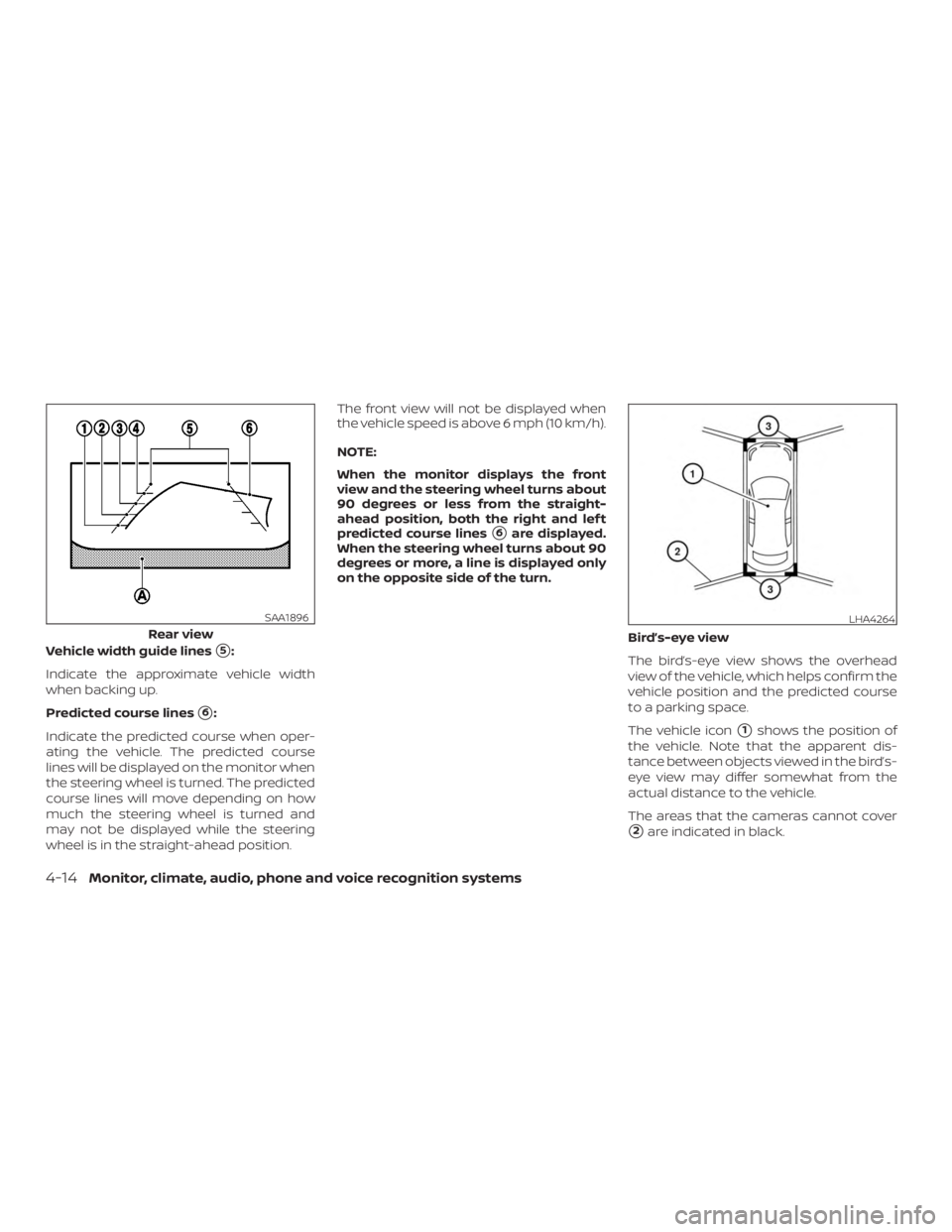
Vehicle width guide lines�5:
Indicate the approximate vehicle width
when backing up.
Predicted course lines
�6:
Indicate the predicted course when oper-
ating the vehicle. The predicted course
lines will be displayed on the monitor when
the steering wheel is turned. The predicted
course lines will move depending on how
much the steering wheel is turned and
may not be displayed while the steering
wheel is in the straight-ahead position. The front view will not be displayed when
the vehicle speed is above 6 mph (10 km/h).
NOTE:
When the monitor displays the front
view and the steering wheel turns about
90 degrees or less from the straight-
ahead position, both the right and lef t
predicted course lines
�6are displayed.
When the steering wheel turns about 90
degrees or more, a line is displayed only
on the opposite side of the turn.
Bird’s-eye view
The bird’s-eye view shows the overhead
view of the vehicle, which helps confirm the
vehicle position and the predicted course
to a parking space.
The vehicle icon
�1shows the position of
the vehicle. Note that the apparent dis-
tance between objects viewed in the bird’s-
eye view may differ somewhat from the
actual distance to the vehicle.
The areas that the cameras cannot cover
�2are indicated in black.
Rear view
SAA1896LHA4264
4-14Monitor, climate, audio, phone and voice recognition systems