Page 112 of 330

3 Pre-driving checks and adjustments
Keys.............................................3-2NISSAN Vehicle Immobilizer System
keys..........................................3-3
Doors ...........................................3-3
Locking with key ..............................3-4
Locking with inside lock knob .................3-5
Locking with power door lock switch
(if so equipped) ...............................3-5
Automatic door locks (if so equipped) ........3-6
Child safety rear door lock ....................3-6
Remote keyless entry system (if so equipped) . . . 3-6 How to use remote keyless entry
system ....................................... 3-7
Hood ............................................3-9 Rear hatch (Hatchback)
........................3-10
Opening the rear hatch ......................3-10
Closing the rear hatch ........................ 3-11
Fuel-filler door ................................... 3-11
Opener operation ............................ 3-11
Fuel-filler cap ................................. 3-11
Steering wheel ................................. 3-14
Tilt operation ................................ 3-14
Sun visors ...................................... 3-14
Vanity mirrors (if so equipped) ...............3-15
Card holder (driver’s side only)
(if so equipped) .............................. 3-15
Mirrors ......................................... 3-15
Rearview mirror ............................. 3-15
Outside mirrors ............................. 3-16
Page 126 of 330
VANITY MIRRORS (if so equipped)
To access the vanity mirror, pull the sun
visor down and flip open the mirror cover.
CARD HOLDER (driver’s side only)
(if so equipped)
To access the card holder, pull the sun visor
down and slide card in the card holder
�A.
Do not view information while operating
the vehicle.
REARVIEW MIRROR
The night position�1reduces glare from
the headlights of vehicles behind you at
night.
Use the day position
�2when driving in
daylight hours.
WARNING
Use the night position only when neces-
sary, because it reduces rear view
clarity.
LPD2586LPD2033WPD0126
MIRRORS
Pre-driving checks and adjustments3-15
Page 127 of 330
OUTSIDE MIRRORS
WARNING
∙ Objects viewed in the outside mirroron the passenger side are closer than
they appear. Be careful when moving
to the right. Using only this mirror
could cause an accident. Use the in-
side mirror or glance over your shoul-
der to properly judge distances to
other objects.
∙ Do not adjust the mirrors while driv- ing. You could lose control of your ve-
hicle and cause an accident.
Manual control type (if so
equipped)
The outside mirror can be moved in any
direction for a better rear view by adjusting
the inside lever.
Electric control type (if so
equipped)
The outside mirror remote control will op-
erate only when the ignition switch is in the
ACC or ON position.
Move the small switch
�1to select the right
or lef t mirror. Adjust each mirror to the de-
sired position using the large switch
�2.
Move the small switch to the center (neu-
tral) position to prevent accidentally mov-
ing the mirror.
LPD2168LPD0237
3-16Pre-driving checks and adjustments
Page 128 of 330
WARNING
∙ Objects viewed in the outside mirroron the passenger side are closer than
they appear. Be careful when moving
to the right. Using only this mirror
could cause an accident. Use the in-
side mirror or glance over your shoul-
der to properly judge distances to
other objects.
∙ Do not adjust the mirrors while driv- ing. You could lose control of your ve-
hicle and cause an accident.
Manual folding outside mirrors
Pull the outside mirror toward the door to
fold it.
Heated mirrors (if so equipped)
The outside mirrors can be heated to de-
frost, defog, or de-ice for improved visibility.
For additional information, refer to “Rear
window and outside mirror (if so equipped)
defroster switch” in the “Instruments and
controls” section of this manual.
WPD0056
Pre-driving checks and adjustments3-17
Page 132 of 330

WARNING
∙ Failure to follow the warnings and in-structions for proper use of the Rear-
View Monitor system could result in
serious injury or death.
∙ RearView Monitor is a convenience feature and is not a substitute for
proper backing. Always turn and look
out the windows and check mirrors to
be sure that it is safe to move before
operating the vehicle. Always back up
slowly.
∙ The system is designed as an aid to the driver in showing large stationary
objects directly behind the vehicle, to
help avoid damaging the vehicle.
∙ The distance guide line and the ve- hicle width line should be used as a
reference only when the vehicle is on a
level paved surface. The distance
viewed on the monitor is for reference
only and may be different than the
actual distance between the vehicle
and displayed objects.
CAUTION
Do not scratch the camera lens when
cleaning dirt or snow from the front of
the camera.
The RearView Monitor system automati-
cally shows a rear view of the vehicle when
the shif t lever is shif ted into the R (Reverse)
position. The radio can still be heard while
the RearView Monitor is active.
To display the rear view, the RearView Moni-
tor system uses a camera located on the
rear hatch near the handle
�1.
REARVIEW MONITOR SYSTEM
OPERATION
With the ignition switch in the ON position,
move the shif t lever to the R (Reverse) po-
sition to operate the RearView Monitor.
LHA4623
Heater, air conditioner, audio and phone systems4-3
Page 136 of 330

∙ Objects viewed in the RearView Moni-tor differ from actual distance be-
cause a wide-angle lens is used.
∙ Objects in the RearView Monitor will appear visually opposite compared to
when viewed in the rearview and out-
side mirrors.
∙ Use the displayed lines as a reference. The lines are highly affected by the
number of occupants, fuel level, ve-
hicle position, road conditions and
road grade.
∙ Make sure that the rear hatch is se- curely closed when backing up.
∙ Do not put anything on the rearview camera. The rearview camera is in-
stalled above the license plate.
∙ When washing the vehicle with high pressure water, be sure not to spray it
around the camera. Otherwise, water
may enter the camera unit causing
water condensation on the lens, a
malfunction, fire or an electric shock.
∙ Do not strike the camera. It is a preci- sion instrument. Otherwise, it may
malfunction or cause damage result-
ing in a fire or an electric shock. The following are operating limitations and
do not represent a system malfunction:
∙ When the temperature is extremely high or low, the screen may not clearly
display objects.
∙ When strong light directly shines on the camera, objects may not be displayed
clearly.
∙ Vertical lines may be seen in objects on the screen. This is due to strong re-
flected light from the bumper.
∙ The screen may flicker under fluores- cent light.
∙ The colors of objects on the RearView Monitor may differ somewhat from the
actual color of objects.
∙ Objects on the monitor may not be clear in a dark environment.
∙ There may be a delay when switching between views.
∙ If dirt, rain or snow accumulate on the camera, RearView Monitor may not dis-
play objects clearly. Clean the camera. ∙ Do not use wax on the camera lens.
Wipe off any wax with a clean cloth
dampened with a diluted mild cleaning
agent, then wipe with a dry cloth.
Heater, air conditioner, audio and phone systems4-7
Page 140 of 330

Fresh airMove the air intake lever to theposi-
tion. The air flow is drawn from outside the
vehicle.
Air recirculation
Move the air intake lever to theposi-
tion to recirculate air inside the vehicle.
Use the
selection:
∙ when driving on a dusty road.
∙ to prevent traffic fumes from entering passenger compartment.
∙ for maximum cooling when using the air conditioner.
Rear window defroster switch
For additional information about the rear
window defroster switch, refer to “Rear win-
dow and outside mirror (if so equipped)
defroster switch” in the “Instruments and
controls” section of this manual.
HEATER OPERATION
Heating
This mode is used to direct heated air to
the foot outlets. Some air also flows from
the defrost outlets.
1. Move the air intake lever to the
position for normal heating.
2. Turn the air flow control dial to the
position.
3. Turn the
fan control dial to the
desired position.
4. Turn the temperature control dial to the desired position between the
middle and the hot position.
Ventilation
This mode directs outside air to the side
and center vents.
1. Move the air intake lever to the
position.
2. Turn the air flow control dial to the
position.
3. Turn the
fan control dial to the
desired position. 4. Turn the temperature control dial to
the desired position.
Defrosting or defogging
This mode directs the air to the defrost
outlets to defrost/defog the windows.
1. Move the air intake lever to the
position.
2. Turn the air flow control dial to the
position.
3. Turn the
fan control dial to the
desired position.
4. Turn the temperature control dial to the desired position between the
middle and the hot position.
5. Align lef t and right vents to direct air flow toward the front side windows.
∙ To quickly remove ice or fog from the windows, turn the fan control dial to the
maximum position and the tempera-
ture control dial to the full hot position.
Heater, air conditioner, audio and phone systems4-11
Page 145 of 330

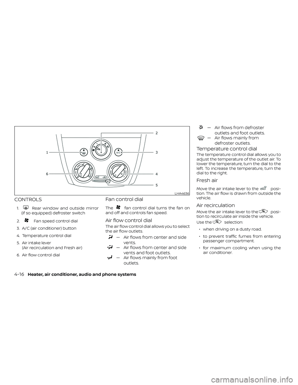
CONTROLS
1.Rear window and outside mirror
(if so equipped) defroster switch
2.
Fan speed control dial
3. A/C (air conditioner) button
4. Temperature control dial
5. Air intake lever (Air recirculation and Fresh air)
6. Air flow control dial
Fan control dial
Thefan control dial turns the fan on
and off and controls fan speed.
Air flow control dial
The air flow control dial allows you to select
the air flow outlets.
— Air flows from center and side
vents.
— Air flows from center and sidevents and foot outlets.
— Air flows mainly from footoutlets.
— Air flows from defroster outlets and foot outlets.
— Air flows mainly fromdefroster outlets.
Temperature control dial
The temperature control dial allows you to
adjust the temperature of the outlet air. To
lower the temperature, turn the dial to the
lef t. To increase the temperature, turn the
dial to the right.
Fresh air
Move the air intake lever to theposi-
tion. The air flow is drawn from outside the
vehicle.
Air recirculation
Move the air intake lever to theposi-
tion to recirculate air inside the vehicle.
Use the
selection:
∙ when driving on a dusty road.
∙ to prevent traffic fumes from entering passenger compartment.
∙ for maximum cooling when using the air conditioner.
LHA4636
4-16Heater, air conditioner, audio and phone systems