Page 236 of 428

one who does not carry the Intelligent Key,
to push the ignition switch to start the en-
gine.
The operating range of the engine start
function is inside of the vehicle
�1.
∙ The luggage area is not included in the operating range, but the Intelligent Key
may function.
∙ If the Intelligent Key is placed on the instrument panel, inside the glove box,
storage bin or door pocket, the Intelli-
gent Key may not function.
∙ If the Intelligent Key is placed near the door or window outside the vehicle, the
Intelligent Key may function.
PUSH-BUTTON IGNITION SWITCH
POSITIONS
LOCK (Normal parking position)
The ignition switch can only be locked in
this position.
The ignition switch will be unlocked when it
is pushed to the ACC position while carry-
ing the Intelligent Key.
The ignition switch will lock when any door
is opened or closed with the ignition
switched off. ACC (Accessories)
This position activates electrical accesso-
ries, such as the radio, when the engine is
not running.
ACC has a battery saver feature that will
place the ignition switch in the OFF position
af ter a period of time under the following
conditions:
∙ All doors are closed.
∙ The shif t lever is in P (Park).
∙ The hazard lamps are off.
∙ The turn signals are off.
The battery saver feature will be canceled if
any of the following occur: ∙ Any door is opened.
∙ The shif t lever is moved out of P (Park).
∙ The ignition switch changes position.
∙ The hazard lamps are turned on.
ON (Normal operating position)
This position turns on the ignition system
and electrical accessories. ON has a battery saver feature that will
place the ignition switch in the OFF posi-
tion, if the vehicle is not running, af ter some
time under the following conditions:
∙ All doors are closed.
∙ The shif t lever is in P (Park).
∙ The hazard lamps are off.
∙ The turn signals are off.
The battery saver feature will be canceled if
any of the following occur: ∙ Any door is opened.
∙ The shif t lever is moved out of the P (Park) position.
∙ The ignition switch changes position.
∙ The hazard lamps are turned on.
∙ The turn signals are turned on.
Page 239 of 428
switch to the LOCK position. Af ter
cranking the engine, release the ac-
celerator pedal. Crank the engine
with your foot off the accelerator
pedal by depressing the brake pedal
and pushing the ignition switch to
start the engine. If the engine starts,
but fails to run, repeat the above pro-
cedure.
Page 242 of 428
WARNING
Apply the parking brake if the shif t lever
is in any position while the engine is not
running. Failure to do so could cause
the vehicle to move unexpectedly or roll
away and result in serious personal in-
jury or property damage.
P (Park)
Page 247 of 428
NORMAL MODE
NORMAL mode is recommended for nor-
mal driving. Press the NORMAL mode but-
ton to select this mode.
SPORT MODE
The SPORT mode adjusts the engine,
transmission, and steering to enhance
performance. Press the SPORT mode but-
ton to select this driving mode. The SPORT
mode indicator will appear in the vehicle
information display.
NOTE:
In the SPORT mode, fuel economy may
be reduced.
Page 305 of 428

WARNING
∙ Do not stop or park the vehicle overflammable materials such as dry
grass, waste paper or rags. They may
ignite and cause a fire. ∙ Safe parking procedures require that
both the parking brake be set and the
transmission placed into P (Park). Fail-
ure to do so could cause the vehicle to
move unexpectedly or roll away and
result in an accident. Make sure the
shif t lever has been pushed as far for-
ward as it can go and cannot be
moved without depressing the foot
brake pedal.
∙ Never leave the engine running while the vehicle is unattended. ∙ To help avoid risk of injury or death
through unintended operation of the
vehicle and/or its systems, do not
leave children, people who require the
assistance of others or pets unat-
tended in your vehicle. Additionally,
the temperature inside a closed ve-
hicle on a warm day can quickly be-
come high enough to cause a signifi-
cant risk of injury or death to people
and pets.
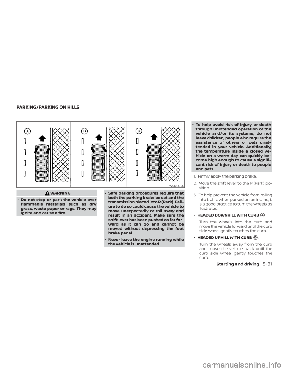
1. Firmly apply the parking brake.
2. Move the shif t lever to the P (Park) po- sition.
3. To help prevent the vehicle from rolling into traffic when parked on an incline, it
is a good practice to turn the wheels as
illustrated.
∙ HEADED DOWNHILL WITH CURB
�A:
Turn the wheels into the curb and
move the vehicle forward until the curb
side wheel gently touches the curb.
∙ HEADED UPHILL WITH CURB
�B:
Turn the wheels away from the curb
and move the vehicle back until the
curb side wheel gently touches the
curb.
Page 307 of 428
The brake system has two separate hy-
draulic circuits. If one circuit malfunctions,
you will still have braking at two wheels.
BRAKE PRECAUTIONS
Vacuum assisted brakes
The brake booster aids braking by using
engine vacuum. If the engine stops, you
can stop the vehicle by depressing the
brake pedal. However, greater foot pres-
sure on the brake pedal will be required to
stop the vehicle and stopping distance will
be longer.
Using the brakes
Avoid resting your foot on the brake pedal
while driving. This will overheat the brakes,
wear out the brake pads faster, and reduce
gas mileage.
To help reduce brake wear and to prevent
the brakes from overheating, reduce speed
and downshif t to a lower gear before going
down a slope or long grade. Overheated
brakes may reduce braking performance
and could result in loss of vehicle control.
Page 309 of 428

WARNING
The Brake Assist is only an aid to assist
braking operation and is not a collision
warning or avoidance device. It is the
driver’s responsibility to stay alert, drive
safely and be in control of the vehicle at
all times.The VDC system uses various sensors to
monitor driver inputs and vehicle motion.
Under certain driving conditions, the VDC
system helps to perform the following
functions:
∙ Controls brake pressure to reduce wheel slip on one slipping drive wheel
so power is transferred to a non-
slipping drive wheel on the same axle.
∙ Controls brake pressure and engine output to reduce drive wheel slip based
on vehicle speed (traction control func-
tion).
∙ Controls brake pressure at individual wheels and engine output to help the
driver maintain control of the vehicle in
the following conditions:
– Understeer (vehicle tends to not fol- low the steered path despite in-
creased steering input)
– Oversteer (vehicle tends to spin due to certain road or driving conditions)
The VDC system can help the driver to
maintain control of the vehicle, but it can-
not prevent loss of vehicle control in all driv-
ing situations. When the VDC system operates, the
Page 312 of 428

The Integrated Dynamics-control Module
is an electric control module that includes
the following functions:∙ Intelligent Trace Control
∙ Intelligent Engine Brake
∙ Active Ride Control
INTELLIGENT TRACE CONTROL
(I-TC)
This system senses driving based on the
driver’s steering and acceleration/braking
patterns, and controls brake pressure at
individual wheels to aid tracing at corners
and help smooth vehicle response.
The I–TC can be set to ON (enabled) or OFF
(disabled) through the vehicle information
display “Settings” page. For additional infor-
mation, refer to “Vehicle information dis-
play” in the “Instruments and controls” sec-
tion of this manual.
When the VDC OFF switch is used to turn off
the VDC system, the I–TC is also turned off.
If the Chassis Control System Error warn-
ing message appears in the vehicle infor-
mation display, it may indicate that the I–TC
is not functioning properly. Have the sys- tem checked as soon as possible. It is rec-
ommended that you visit a NISSAN dealer
for this service.