Page 192 of 592
Lockout protection
To prevent the Intelligent Key from being
accidentally locked in the trunk, lockout
protection is equipped with the Intelligent
Key.
When all doors are locked and the trunk lid
is closed with the Intelligent Key inside the
trunk, the outside buzzer will sound and the
trunk will open.
HOW TO USE THE REMOTE
KEYLESS ENTRY FUNCTION
The remote keyless entry function can op-
erate all door locks using the remote key-
less function of the Intelligent Key. The re-
mote keyless function can operate at a
distance of 33 f t (10 m) away from the ve-
hicle. The operating distance depends
upon the conditions around the vehicle.
The remote keyless entry function may not
function under the following conditions:∙ When the Intelligent Key is not within the operational range.
∙ When the doors or the trunk are open or not closed securely.
∙ When the Intelligent Key battery is dis- charged.
Page 271 of 592

WARNING
Do not operate the push-button igni-
tion switch while driving the vehicle ex-
cept in an emergency. (The engine will
stop when the ignition switch is pushed
three consecutive times in quick suc-
cession or the ignition switch is pushed
and held for more than 2 seconds.) If the
engine stops while the vehicle is being
driven, this could lead to a crash and
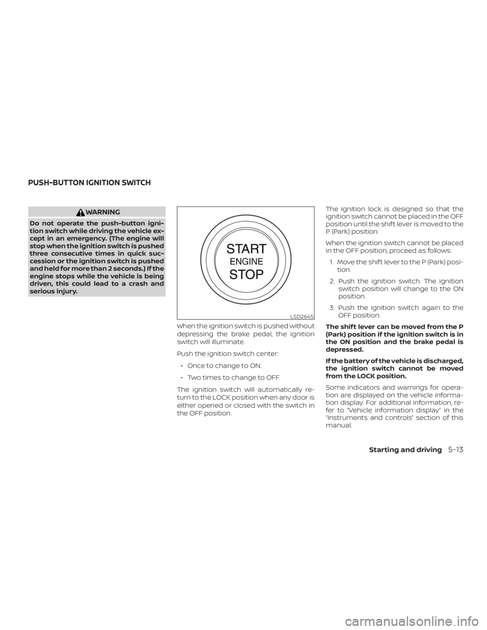
serious injury.When the ignition switch is pushed without
depressing the brake pedal, the ignition
switch will illuminate.
Push the ignition switch center:∙ Once to change to ON.
∙ Two times to change to OFF.
The ignition switch will automatically re-
turn to the LOCK position when any door is
either opened or closed with the switch in
the OFF position. The ignition lock is designed so that the
ignition switch cannot be placed in the OFF
position until the shif t lever is moved to the
P (Park) position.
When the ignition switch cannot be placed
in the OFF position, proceed as follows:
1. Move the shif t lever to the P (Park) posi- tion.
2. Push the ignition switch. The ignition switch position will change to the ON
position.
3. Push the ignition switch again to the OFF position.
The shif t lever can be moved from the P
(Park) position if the ignition switch is in
the ON position and the brake pedal is
depressed.
If the battery of the vehicle is discharged,
the ignition switch cannot be moved
from the LOCK position.
Some indicators and warnings for opera-
tion are displayed on the vehicle informa-
tion display. For additional information, re-
fer to “Vehicle information display” in the
“Instruments and controls” section of this
manual.
Page 272 of 592

OPERATING RANGE
The Intelligent Key functions can only be
used when the Intelligent Key is within the
specified operating range.
When the Intelligent Key battery is almost
discharged or strong radio waves are pres-
ent near the operating location, the Intelli-
gent Key system’s operating range becomes
narrower and may not function properly.
If the Intelligent Key is within the operating
range, it is possible for anyone, even some-
one who does not carry the Intelligent Key, to
push the ignition switch to start the engine.
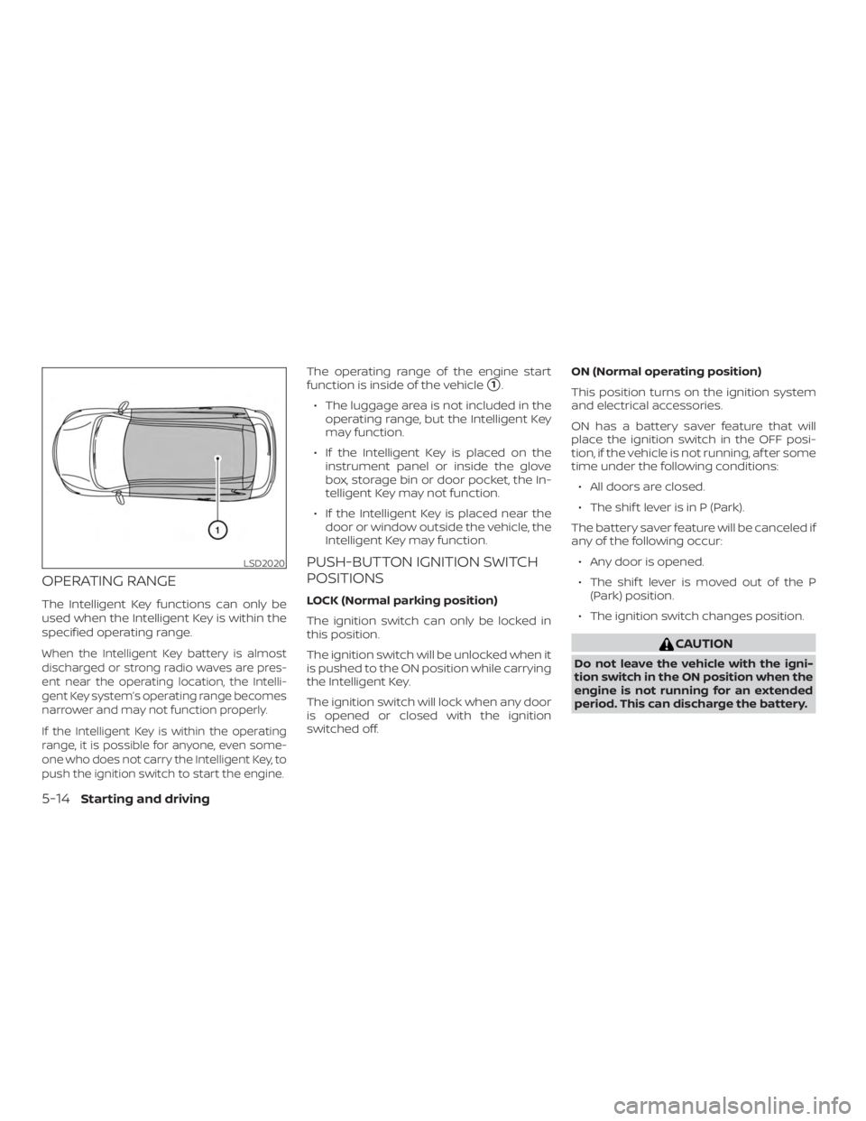
The operating range of the engine start
function is inside of the vehicle
�1.
∙ The luggage area is not included in the operating range, but the Intelligent Key
may function.
∙ If the Intelligent Key is placed on the instrument panel or inside the glove
box, storage bin or door pocket, the In-
telligent Key may not function.
∙ If the Intelligent Key is placed near the door or window outside the vehicle, the
Intelligent Key may function.
PUSH-BUTTON IGNITION SWITCH
POSITIONS
LOCK (Normal parking position)
The ignition switch can only be locked in
this position.
The ignition switch will be unlocked when it
is pushed to the ON position while carrying
the Intelligent Key.
The ignition switch will lock when any door
is opened or closed with the ignition
switched off. ON (Normal operating position)
This position turns on the ignition system
and electrical accessories.
ON has a battery saver feature that will
place the ignition switch in the OFF posi-
tion, if the vehicle is not running, af ter some
time under the following conditions:
∙ All doors are closed.
∙ The shif t lever is in P (Park).
The battery saver feature will be canceled if
any of the following occur: ∙ Any door is opened.
∙ The shif t lever is moved out of the P (Park) position.
∙ The ignition switch changes position.
Page 451 of 592
WARNING
∙ Always make sure that the spare tireand jacking equipment are properly
secured af ter use. Such items can be-
come dangerous projectiles in an ac-
cident or sudden stop.
∙ The spare tire is designed for emer- gency use. For additional information,
refer to “Wheels and tires” in the “Do-
it-yourself ” section of this manual. To start your engine with a booster battery,
the instructions and precautions below
must be followed.
Page 452 of 592
WARNING
Always follow the instructions below.
Failure to do so could result in damage
to the charging system and cause per-
sonal injury.1. If the booster battery is in another ve- hicle, position the two vehicles to bring
their batteries near each other.
Do not allow the two vehicles to
touch. 2. Apply the parking brake. Move the shif t
lever to P (Park). Switch off all unneces-
sary electrical systems (lights, heater,
air conditioner, etc.).
3. Place the ignition switch in the LOCK position.
4. Connect the jumper cables in the se- quence illustrated (
�A,�B,�C,�D).
Page 481 of 592
Caution symbols for battery
Page 482 of 592
NOTE:
Care should be taken to avoid situations
that can lead to potential battery dis-
charge and potential no-start conditions
such as:1. Installation or extended use of elec-
tronic accessories that consume bat-
tery power when the engine is not
running (Phone chargers, GPS, DVD
players, etc.)
2. Vehicle is not driven regularly and/or
only driven short distances.
In these cases, the battery may need to
be charged to maintain battery health.
Page 483 of 592
CAUTION
∙ Do not ground accessories directly tothe battery terminal. Doing so will by-
pass the variable voltage control sys-
tem and the vehicle battery may not
charge completely.
∙ Use electrical accessories with the en- gine running to avoid discharging the
vehicle battery. Your vehicle is equipped with a variable
voltage control system. This system mea-
sures the amount of electrical discharge
from the battery and controls voltage gen-
erated by the generator.
The current sensor is located near the bat-
tery along the negative battery cable. If you
add electrical accessories to your vehicle,
be sure to ground them to a suitable body
ground such as the frame or engine block
area.
1. Automatic tensioner pulley
2. Generator pulley
3. Water pump pulley
4. Air conditioner compressor pulley
5. Crankshaf t pulley