Page 26 of 467
QR25DE engine
1. Power steering fluid reservoir(P. 8-11)
2. Engine coolant reservoir (P. 8-5)
3. Engine oil filler cap (P. 8-7)
4. Brake fluid reservoir (P. 8-12)
5. Air cleaner (P. 8-18)
6. Fuse/Fusible link box (P. 8-21)
7. Battery (P. 8-14)
8. Engine oil dipstick (P. 8-7)
9. Radiator cap (P. 8-5)
10. Drive belt location (P. 8-16)
11. Windshield-washer fluid reservoir
(P. 8-13)
Refer to the page number indicated in
parentheses for operating details.
LDI2111
ENGINE COMPARTMENT CHECK
LOCATIONS
0-8Illustrated table of contents
Page 27 of 467
VQ35DE engine
1. Power steering fluid reservoir(P. 8-11)
2. Engine coolant reservoir (P. 8-5)
3. Engine oil filler cap (P. 8-7)
4. Brake fluid reservoir (P. 8-12)
5. Air cleaner (P. 8-18)
6. Fuse/Fusible link box (P. 8-21)
7. Battery (P. 8-14)
8. Engine oil dipstick (P. 8-7)
9. Radiator cap (P. 8-5)
10. Drive belt location (P. 8-16)
11. Windshield-washer fluid reservoir
(P. 8-13)
Refer to the page number indicated in
parentheses for operating details.
LDI2112
Illustrated table of contents0-9
Page 92 of 467

2 Instruments and controls
Instrument panel................................2-2
Meters and gauges ..............................2-3
Speedometer and odometer .................2-4
Tachometer ..................................2-5
Engine coolant temperature gauge ..........2-5
Fuel gauge ...................................2-6
Compass (if so equipped) ....................... 2-7
Compass display ............................. 2-7
Warning lights, indicator lights and audible
reminders ...................................... 2-10
Checking lights .............................. 2-10
Warning lights ................................ 2-11
Indicator lights .............................. 2-15
Audible reminders ........................... 2-17
Vehicle information display .....................2-18
How to use the vehicle information
display ...................................... 2-19
Startup display .............................. 2-19
Resetting the trip computer .................2-19
Settings ..................................... 2-19
Vehicle information display warnings
and indicators ............................... 2-27
Security systems ............................... 2-31
Vehicle security system .....................2-31NISSAN Vehicle Immobilizer System
.........2-32
Wiper and washer switch .......................2-34
Switch operation ............................ 2-34
Rear window and outside mirror
(if so equipped) defroster switch ................2-35
Headlight and turn signal switch ...............2-35
Headlight control switch .....................2-35
Daytime Running Lights (DRL) system
(Type A) (if so equipped) .....................2-38
LED Daytime Running Lights (DRL)
system (Type B) (if so equipped) .............2-38
Instrument brightness control ...............2-39
Turn signal switch ........................... 2-39
Fog light switch (if so equipped) .............2-40
Horn ........................................... 2-40
Heated seat switches (if so equipped) ..........2-41
Heated steering wheel switch (if so equipped) . . 2-42
Vehicle Dynamic Control (VDC) OFF switch ......2-42
E-c
all (SOS) switch (if so equipped) ..............2-43
Power outlets .................................. 2-43
Extended storage switch .......................2-44
Storage ........................................ 2-45
Front-door pockets .......................... 2-45
Seatback pockets ........................... 2-46
Page 95 of 467

16. USB connection port(if so equipped) (P. 4-24)
Aux jack (P. 4-24)
17. Push-button ignition switch
(P. 5-9)
18. Cruise control main/set switches
(if so equipped) (P. 5-41)")
15. Shif t lever (P. 5-14)
16. USB connection port(if so equipped) (P. 4-24)
Aux jack (P. 4-24)
17. Push-button ignition switch
(P. 5-9)
18. Cruise control main/set switches
(if so equipped) (P. 5-41)
Intelligent Cruise Control (ICC)
switches (if so equipped) (P. 5-43)
Bluetooth® Hands-free Phone
System (P. 4-2, 4-54)
19. Tilt/telescopic steering wheel
controls (P. 3-28)
20. Vehicle information display
controls (P. 2-18)
Steering wheel switch for audio
control (P. 4-48)
21. Hood release (P. 3-23)
22. Trunk opener (P. 3-24) Vehicle Dynamic Control (VDC) OFF
switch (P. 2-42)
Heated steering wheel switch
(if so equipped) (P. 2-42)
*: For additional information, refer to the
separate NissanConnect® Owner’s Manual.
Refer to the page number indicated in
parentheses for operating details.
1. Tachometer
2. Warning and indicator lights
3. Vehicle information displayOdometer
Twin trip odometer
4. Speedometer 5. Fuel gauge
6. Engine coolant temperature gauge
LIC3459
METERS AND GAUGES
Instruments and controls2-3
Page 97 of 467
Changing the display
Push the TRIP RESET switch
�2on the lef t
side of the instrument panel to change the
display as follows:
Trip
→ Trip→ Odometer Mile-
age →Trip
Resetting the trip odometer
Pushing the TRIP RESET switch
�2for more
than 1 second resets the currently dis-
played trip odometer to zero.
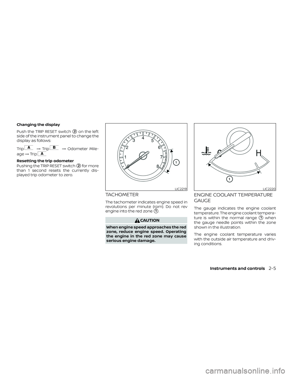
TACHOMETER
The tachometer indicates engine speed in
revolutions per minute (rpm). Do not rev
engine into the red zone
�1.
CAUTION
When engine speed approaches the red
zone, reduce engine speed. Operating
the engine in the red zone may cause
serious engine damage.
ENGINE COOLANT TEMPERATURE
GAUGE
The gauge indicates the engine coolant
temperature. The engine coolant tempera-
ture is within the normal range
�1when
the gauge needle points within the zone
shown in the illustration.
The engine coolant temperature varies
with the outside air temperature and driv-
ing conditions.
LIC2219LIC2220
Instruments and controls2-5
Page 98 of 467
 end of the normal
range, reduce vehicle speed to decrease
temperature. If the gauge is over the
normal range, stop the vehicle as")
CAUTION
If the gauge indicates coolant tempera-
ture near the hot (H) end of the normal
range, reduce vehicle speed to decrease
temperature. If the gauge is over the
normal range, stop the vehicle as soon
as safely possible. If the engine is over-
heated, continued operation of the ve-
hicle may seriously damage the engine.
For additional information, refer to “If
your vehicle overheats” in the “In case
of emergency ” section of this manual
for immediate action required.
FUEL GAUGE
The gauge indicates theapproximatefuel
level in the tank.
The gauge may move slightly during brak-
ing, turning, acceleration, or going up or
down hills.
The gauge needle returns to 0 (Empty) af-
ter the ignition switch is placed in the OFF
position.
The low fuel warning message shows in
the vehicle information display when the
amount of fuel in the tank is getting low. Refill the fuel tank before the gauge reg-
isters 0 (Empty).
The
indicates that the fuel-filler
door is located on the driver’s side of the
vehicle.
CAUTION
∙ If the vehicle runs out of fuel, theMalfunction Indicator Light (MIL) may
come on. Refuel as soon as possible.
Af ter a few driving trips, the
light
should turn off. If the light remains on
af ter a few driving trips, have the ve-
hicle inspected. It is recommended
that you visit a NISSAN dealer for this
service.
∙ For additional information, refer to “Malfunction Indicator Light (MIL)” in
this section.
LIC2222
2-6Instruments and controls
Page 203 of 467
∙ A visible mist may be seen coming fromthe ventilators in hot, humid conditions
as the air is cooled rapidly. This does not
indicate a malfunction.
∙ If the engine coolant temperature
gauge indicates engine coolant tem-
perature over the normal range, turn
the air conditioner off. For additional
information, refer to “If your vehicle
overheats” in the “In case of emer-
gency ” section of this manual.
AIR FLOW CHARTS
The following charts show the button and
dial positions for MAXIMUM AND QUICK
heating, cooling or defrosting. The air re-
circulation button should always be in
the OFF position for heating and defrost-
ing.
LHA3787
Monitor, climate, audio, phone and voice recognition systems4-17
Page 209 of 467
 defroster switch
For additional information, refer to “Rear
window and outside mirror (if so equipped)
def")
To turn system off
Press the ON-OFF button.
Rear window and outside mirror
(if so equipped) defroster switch
For additional information, refer to “Rear
window and outside mirror (if so equipped)
defroster switch” in the “Instruments and
controls” section of this manual.
OPERATING TIPS
The sunload sensor, located on the top
driver’s side of the instrument panel, helps
the system maintain a constant tempera-
ture. Do not put anything on or around this
sensor.∙ When the climate system is in auto-
matic operation and the engine coolant
temperature and outside air tempera-
ture are low, the air flow outlet may de-
fault to defroster mode for a maximum
of 2 minutes 30 seconds. This is not a
malfunction. Af ter the engine coolant
temperature warms up, the air flow out-
let will return to foot mode and opera-
tion will continue normally.
∙ When the outside and interior cabin temperatures are moderate to high, the
intake setting may default to turn off air
recirculation to allow fresh air into the
passenger compartment. You may no-
tice air flow from the foot mode, bi-level
mode, or side demist vent outlets for a
maximum of 15 seconds. This may oc-
cur when previous climate setting was
system off. This is not a malfunction.
Af ter the initial warm air is expelled, the
intake will return to automatic control,
air flow outlet will return to previous set-
tings, and operation will continue nor-
mally. To exit, press any climate control
button.
∙ Keep the moonroof (if so equipped) closed while the air conditioner is in op-
eration.
LHA1136
Monitor, climate, audio, phone and voice recognition systems4-23

2. Engine coolant reservoir (P. 8-5)
3. Engine oil filler cap (P. 8-7)
4. Brake fluid reservoir (P. 8-12)
5. Air cleaner (P. 8-18)
6. Fuse/Fusi")

2. Engine coolant reservoir (P. 8-5)
3. Engine oil filler cap (P. 8-7)
4. Brake fluid reservoir (P. 8-12)
5. Air cleaner (P. 8-18)
6. Fuse/Fusi")