2018 NISSAN 370Z COUPE automatic transmission
[x] Cancel search: automatic transmissionPage 20 of 453

0-10Illustrated table of contents
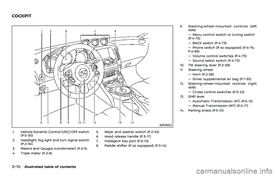
SSI0652
1. Vehicle Dynamic Control (VDC) OFF switch(P.5-30)
2. Headlight, fog light and turn signal switch (P.2-34)
3. Meters and Gauges (combimeter) (P.2-5)
4. Triple meter (P.2-8) 5. Wiper and washer switch (P.2-32)
6. Hood release handle (P.3-17)
7. Intelligent Key port (P.5-10)
8. Paddle shifter (if so equipped) (P.5-14)9. Steering-wheel-mounted controls (left
side)
— Menu control switch or tuning switch
(P.4-73)
— BACK switch (P.4-73)
— Phone switch (if so equipped) (P.4-76,
P.4-86)
— Volume control switches (P.4-73)
— Source select switch (P.4-73)
10. Tilt steering lever (P.3-38)
11. Steering wheel
— Horn (P.2-38)
— Driver supplemental air bag (P.1-30)
12. Steering-wheel-mounted controls (right side)
— Cruise control switches (P.5-22)
13. Shift lever
— Automatic Transmission (AT) (P.5-12)
— Manual Transmission (MT) (P.5-17)
14. Parking brake (P.5-21)
COCKPIT
Page 24 of 453

0-14Illustrated table of contents
Warninglight Name
Page
Anti-lock Braking System
(ABS) warning light 2-11
Automatic Transmission
(AT) check warning light (if
so equipped)2-11
Brake warning light
2-11
Charge warning light2-12
Engine oil pressure warning
light2-12
Intelligent Key system
warning light
2-12
Low tire pressure warning
light2-13
Master warning light
2-14
Seat belt warning light2-14
Supplemental air bag
warning light2-14
Vehicle Dynamic Control
(VDC) warning light 2-15Indica-
tor light Name
Page
Cruise indicator light 2-15
Exterior light indicator2-15
Front passenger air bag
status light2-16
High beam indicator light
2-16
Malfunction Indicator Light
(MIL)2-16
Rear fog light indicator light
(if so equipped) 2-17
Security indicator light
2-17
Soft top indicator light
(Roadster models)2-17
SynchroRev Match mode
(S-MODE) indicator (if so
equipped)2-17
Transmission position indi-
cator light (if so equipped)
2-18
Turn signal/hazard indica-
tor lights
2-18
Vehicle Dynamic Control
(VDC) off indicator light2-18
WARNING AND INDICATOR LIGHTS
Page 73 of 453

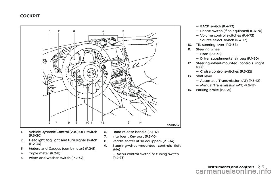
SSI0652
1. Vehicle Dynamic Control (VDC) OFF switch(P.5-30)
2. Headlight, fog light and turn signal switch (P.2-34)
3. Meters and Gauges (combimeter) (P.2-5)
4. Triple meter (P.2-8)
5. Wiper and washer switch (P.2-32) 6. Hood release handle (P.3-17)
7. Intelligent Key port (P.5-10)
8. Paddle shifter (if so equipped) (P.5-14)
9. Steering-wheel-mounted controls (left
side)
— Menu control switch or tuning switch
(P.4-73) — BACK switch (P.4-73)
— Phone switch (if so equipped) (P.4-76)
— Volume control switches (P.4-73)
— Source select switch (P.4-73)
10. Tilt steering lever (P.3-38)
11. Steering wheel — Horn (P.2-38)
— Driver supplemental air bag (P.1-30)
12. Steering-wheel-mounted controls (right side)
— Cruise control switches (P.5-22)
13. Shift lever — Automatic Transmission (AT) (P.5-12)
— Manual Transmission (MT) (P.5-17)
14. Parking brake (P.5-21)
Instruments and controls2-3
COCKPIT
Page 80 of 453

2-10Instruments and controls
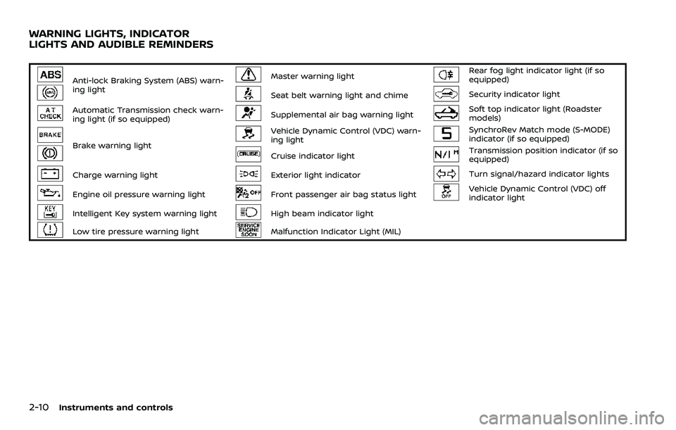
Anti-lock Braking System (ABS) warn-
ing lightMaster warning lightRear fog light indicator light (if so
equipped)
Seat belt warning light and chimeSecurity indicator light
Automatic Transmission check warn-
ing light (if so equipped)Supplemental air bag warning lightSoft top indicator light (Roadster
models)
Brake warning light
Vehicle Dynamic Control (VDC) warn-
ing lightSynchroRev Match mode (S-MODE)
indicator (if so equipped)
Cruise indicator lightTransmission position indicator (if so
equipped)
Charge warning lightExterior light indicatorTurn signal/hazard indicator lights
Engine oil pressure warning lightFront passenger air bag status lightVehicle Dynamic Control (VDC) off
indicator light
Intelligent Key system warning lightHigh beam indicator light
Low tire pressure warning lightMalfunction Indicator Light (MIL)
WARNING LIGHTS, INDICATOR
LIGHTS AND AUDIBLE REMINDERS
Page 81 of 453

CHECKING LIGHTS
With all doors closed, apply the parking
brake, fasten the seat belts and place the
ignition switch in the ON position without
starting the engine. The following lights (if
so equipped) will come on:
,or,,
The following lights (if so equipped) come
on briefly and then go off:
,or,,,,,
If any light does not come on or operates
in a way other than described, it may
indicate a burned-out bulb and/or a
system malfunction. It is recommended
you have the system checked by a
NISSAN dealer.
Some indicators and warnings are also
displayed on the vehicle information dis-
play. (See “Vehicle information display”
(P.2-19).)
WARNING LIGHTS
orAnti-lock Braking Sys-
tem (ABS) warning light
When the ignition switch is in the ON
position, the Anti-lock Braking System
(ABS) warning light illuminates and then
turns off. This indicates the ABS is opera-
tional.
If the ABS warning light illuminates while
the engine is running, or while driving, it
may indicate the ABS is not functioning
properly. Have the system checked. It is
recommended you visit a NISSAN dealer
for this service.
If an ABS malfunction occurs, the anti-
lock function is turned off. The brake
system then operates normally, but with-
out anti-lock assistance. (See “Brake sys-
tem” (P.5-27).)
Automatic transmission check
warning light (if so equipped)
When the ignition switch is pushed to the
ON position, the light comes on for 2
seconds. If the light comes on at any
other time, it may indicate the transmis-
sion is not functioning properly. It is
recommended you visit a NISSAN dealer
to check and repair the transmission.
orBrake warning light
This light functions for both the parking
brake and the foot brake systems.
Parking brake indicator:
When the ignition switch is in the ON
position, the light comes on when the
parking brake is applied.
Low brake fluid warning light:
When the ignition switch is in the ON
position, the light warns of a low brake
fluid level. If the light comes on while the
engine is running with the parking brake
not applied, stop the vehicle and perform
the following:
1. Check the brake fluid level. Add brake
fluid as necessary. (See “Brake and
clutch fluid” (P.8-9).)
2. If the brake fluid level is correct, have the warning system checked. It is
recommended you have this service
performed by a NISSAN dealer.
Anti-lock Braking System (ABS) warning
indicator:
When the parking brake is released and
the brake fluid level is sufficient, if both
the brake warning light and the Anti-lock
Braking System (ABS) warning light illu-
minate, it may indicate the ABS is not
functioning properly. Have the brake
Instruments and controls2-11
Page 89 of 453

SIC3977
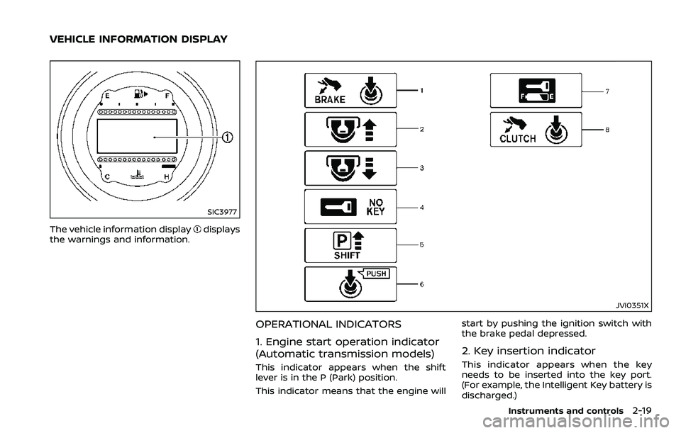
The vehicle information displaydisplays
the warnings and information.
JVI0351X
OPERATIONAL INDICATORS
1. Engine start operation indicator
(Automatic transmission models)
This indicator appears when the shift
lever is in the P (Park) position.
This indicator means that the engine will start by pushing the ignition switch with
the brake pedal depressed.
2. Key insertion indicator
This indicator appears when the key
needs to be inserted into the key port.
(For example, the Intelligent Key battery is
discharged.)
Instruments and controls2-19
VEHICLE INFORMATION DISPLAY
Page 90 of 453

2-20Instruments and controls
If this indicator appears, insert the key
into the key port in the correct direction.
(See “Push-button ignition switch” (P.5-8).)
3. Intelligent Key removal indicator
This indicator appears when the driver’s
door is opened with the ignition switch in
the OFF or LOCK position and the Intelli-
gent Key placed in the key port. A key
reminder chime also sounds.
If this indicator appears, remove the
Intelligent Key from the key port and take
it with you when leaving the vehicle.
4. NO KEY warning
This warning appears in either of the
following conditions.
No Intelligent Key inside the vehicle:
The warning appears when the door is
closed with the Intelligent Key left outside
the vehicle and the ignition switch in the
ACC or ON position. Make sure that the
Intelligent Key is inside the vehicle.
Unregistered Intelligent Key:
The warning appears when the ignition
switch is pushed from the LOCK position
and the Intelligent Key cannot be recog-
nized by the system. You cannot start the
engine with an unregistered key. Use the
registered Intelligent Key.
See “Intelligent Key system” (P.3-7) formore details.
5. SHIFT “P” warning (Automatic
Transmission models)
This warning appears when the ignition
switch is pushed to stop the engine with
the shift lever in any position except the P
(Park) position.
If this warning appears, move the shift
lever to the P (Park) position or push the
ignition switch to the ON position.
An inside warning chime will also sound.
(See “Intelligent Key system” (P.3-7).)
6. “PUSH” warning (Automatic
Transmission models)
This warning appears when the shift lever
is moved to the P (Park) position with the
ignition switch in the ACC position after
the SHIFT “P” warning appears.
To push the ignition switch to the OFF
position, perform the following proce-
dure:
SHIFT “P” warning
?(Move the shift lever
to “P”) ?PUSH warning ?(Push the
ignition switch ?ignition switch position
is turned to ON) ?PUSH warning ?
(Push the ignition switch ?ignition
switch position is turned to OFF)
7. Intelligent Key battery discharge
indicator
This indicator appears when the Intelli-
gent Key battery is running out of power.
If this indicator appears, replace the
battery with a new one. (See “Intelligent
Key battery replacement” (P.8-20).)
8. Engine start operation indicator
(Manual Transmission models)
This indicator means that the engine will
start by pushing the ignition switch with
the clutch pedal depressed.
Page 124 of 453

2-54Instruments and controls
JVI0429X
3. Press and hold the programmedHomeLink® button and observe the
indicator light.
.If the indicator lightis solid/
continuous, programming is com-
plete and your device should acti-
vate when the HomeLink® button is
pressed and released.
.If the indicator lightblinks rapidly
for two seconds and then turns to a
solid/continuous light, continue
with Steps 4-6 for a rolling code
device. A second person may make
the following steps easier. Use a
ladder or other device. Do not stand
on your vehicle to perform the next
steps. 4. At the receiver located on the garage
door opener motor in the garage,
locate the “learn” or “smart” button
(the name and color of the button
may vary by manufacturer but it is
usually located near where the hang-
ing antenna wire is attached to the
unit). If there is difficulty locating the
button, reference the garage door
opener’s manual.
5. Press and release the “learn” or “smart” button.
NOTE:
Once the button is pressed, you have
approximately 30 seconds to initiate
the next step.
6. Return to the vehicle and firmly press and hold the programmed HomeLink®
button for two seconds and release.
Repeat the “press/hold/release” se-
quence up to 3 times to complete
the programming process. HomeLink®
should now activate your rolling code
equipped device.
7. If you have any questions or are having difficulty programming your
HomeLink® buttons, refer to the
HomeLink® web site at: www.
homelink.com or call 1-800-355-3515.
PROGRAMMING HomeLink® FOR
CANADIAN CUSTOMERS AND GATE
OPENERS
Canadian radio-frequency laws require
transmitter signals to “time-out” (or quit)
after several seconds of transmission –
which may not be long enough for
HomeLink® to pick up the signal during
programming. Similar to this Canadian
law, some U.S. gate operators are de-
signed to “time-out” in the same manner.
If you live in Canada or you are having
difficulties programming a gate operator
or garage door opener by using the
“Programming HomeLink®” procedures,
replace “Programming HomeLink®” Step
2 with the following:
NOTE:
When programming a garage door
opener, etc., unplug the device during
the “cycling” process to prevent possi-
ble damage to the garage door opener
components.
Step 2: Using both hands, simultaneously
press and hold the desired HomeLink®
button and the hand-held transmitter
button. During programming, your hand-
held transmitter may automatically stop
transmitting. Continue to press and hold
the desired HomeLink® button while you
press and re-press (“cycle”) your hand-