Page 95 of 441

Free-hand Advanced
Security Transmitter (F.A.S
.T.-key) (if so equipped)
5
N00503201177
When a person enters the operating range ofthe F.A.S.T.-key while carrying the F.A.S.T.-key and presses the driver’s or front passen-ger’s door lock/unlock switch, the liftgateLOCK switch or the liftgate OPEN switch,verification of the ID
code is performed.
The doors and the liftgate can be locked andunlocked and the engine
can be started only
when the ID codes of the vehicle andF.A.S.T.-key match.
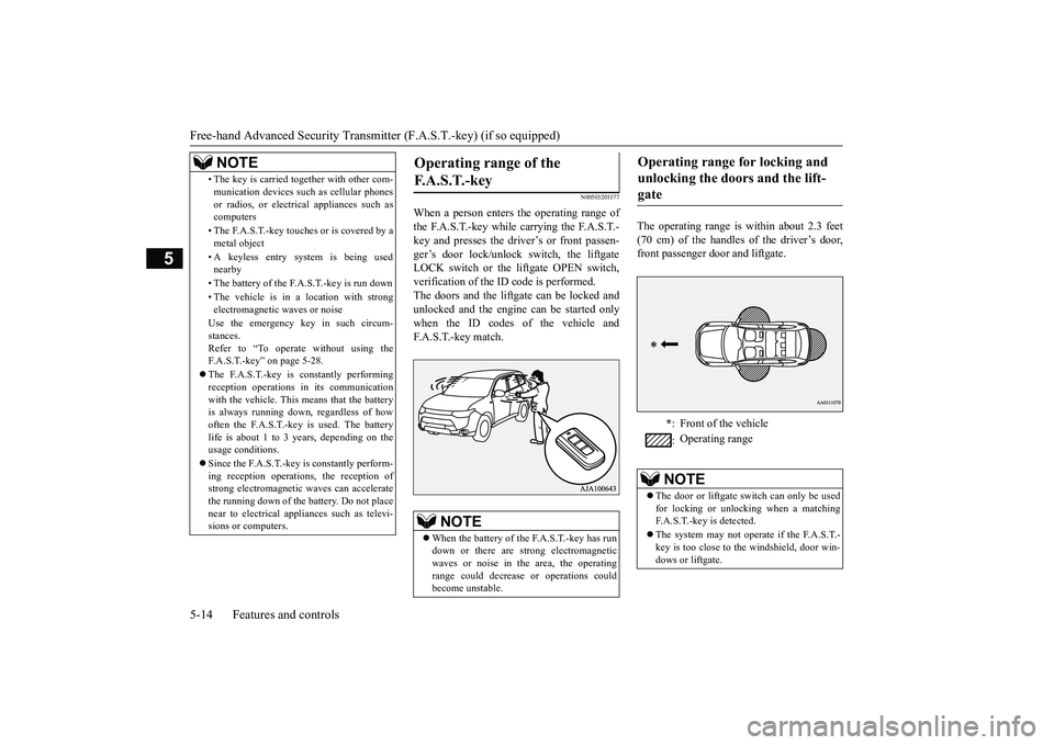
The operating range is
within about 2.3 feet
(70 cm) of the handles of the driver’s door,front passenger door and liftgate.
• The key is carried together with other com-munication devices such
as cellular phones
or radios, or electrical appliances such ascomputers• The F.A.S.T.-key touches or is covered by ametal object• A keyless entry system is being usednearby• The battery of the F.A.S.T.-key is run down• The vehicle is in
a location with strong
electromagnetic
waves or noise
Use the emergency key in such circum-stances.Refer to “To operate
without using the
F.A.S.T.-key” on page 5-28.The F.A.S.T.-key is constantly performingreception opera
tions in its communication
with the vehicle. This means that the batteryis always running down, regardless of howoften the F.A.S.T.-key is used. The batterylife is about 1 to 3 years, depending on theusage conditions.Since the F.A.S.T.-key is constantly perform-ing reception operati
ons, the reception of
strong electrom
agnetic waves
can accelerate
the running down of the ba
ttery. Do not place
near to electrical appliances such as televi-sions or computers.NOTE
Operating range of the F. A . S . T. - k e y
NOTE
When the battery of the F.A.S.T.-key has rundown or there are st
rong electromagnetic
waves or noise in the area, the operatingrange could decrease
or operations could
become unstable.
Operating range for locking and unlocking the doors and the lift-gate
*: Front of the vehicle:Operating range
NOTE
The door or liftgate switch can only be usedfor locking or unlocking when a matchingF.A.S.T.-key is detected.The system may not operate if the F.A.S.T.-key is too close to the windshield, door win-dows or liftgate.
BK0249100US.book 14 ページ 2017年5月10日 水曜日 午前8時49分
Page 127 of 441

Inside liftgate release5-46 Features and controls
5
N00523101084
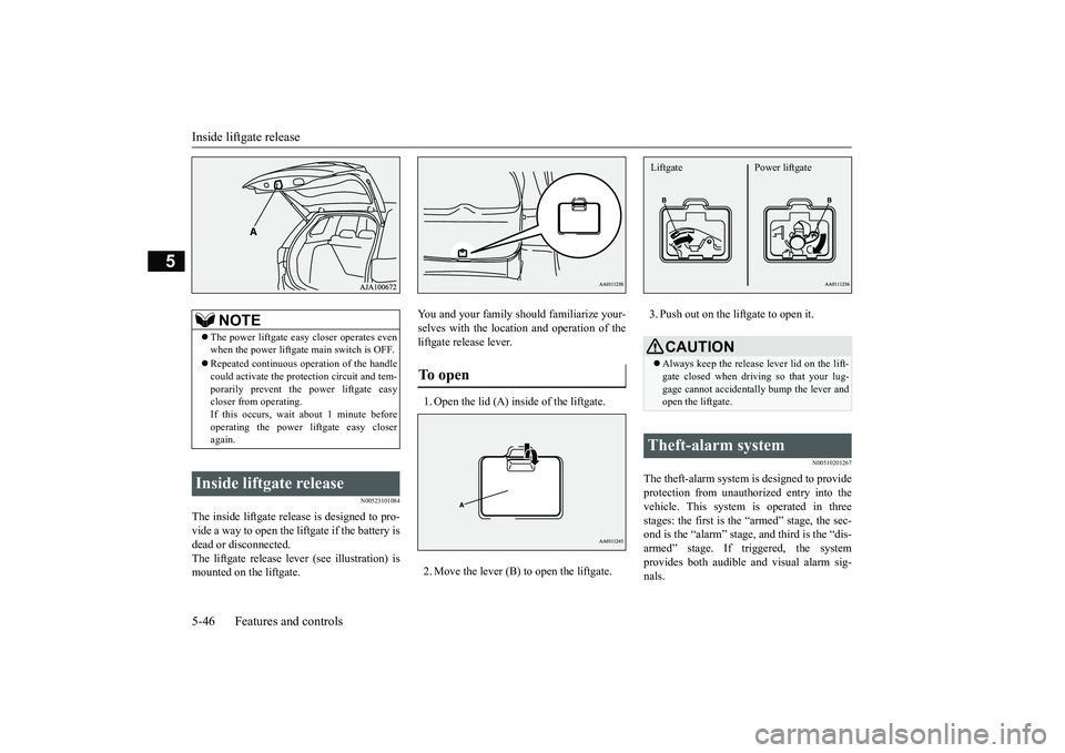
The inside liftgate release is designed to pro-vide a way to open the liftgate if the battery isdead or disconnected.The liftgate release lever (see illustration) ismounted on the liftgate.
You and your family should familiarize your-selves with the location and operation of theliftgate release lever.1. Open the lid (A) inside of the liftgate.2. Move the lever (B) to open the liftgate.
3. Push out on the liftgate to open it.
N00510201267
The theft-alarm system is designed to provideprotection from unauthorized entry into thevehicle. This system
is operated in three
stages: the first is the “armed” stage, the sec-ond is the “alarm” stage, and third is the “dis-armed” stage. If triggered, the systemprovides both audible and visual alarm sig-nals.
NOTE
The power liftgate easy closer operates evenwhen the power liftgate main switch is OFF.Repeated continuous ope
ration of the handle
could activate the prot
ection circui
t and tem-
porarily prevent the
power liftgate easy
closer from operating.If this occurs, wait
about 1 minute before
operating the power liftgate easy closeragain.
Inside liftgate release
To open
CAUTIONAlways keep the release lever lid on the lift-gate closed when driving so that your lug-gage cannot acci
dentally bump the lever and
open the liftgate.
Theft-alarm system Liftgate Power liftgate
BK0249100US.book 46 ページ 2017年5月10日 水曜日 午前8時49分
Page 364 of 441

Jump-starting the engineFor emergencies 8-3
8
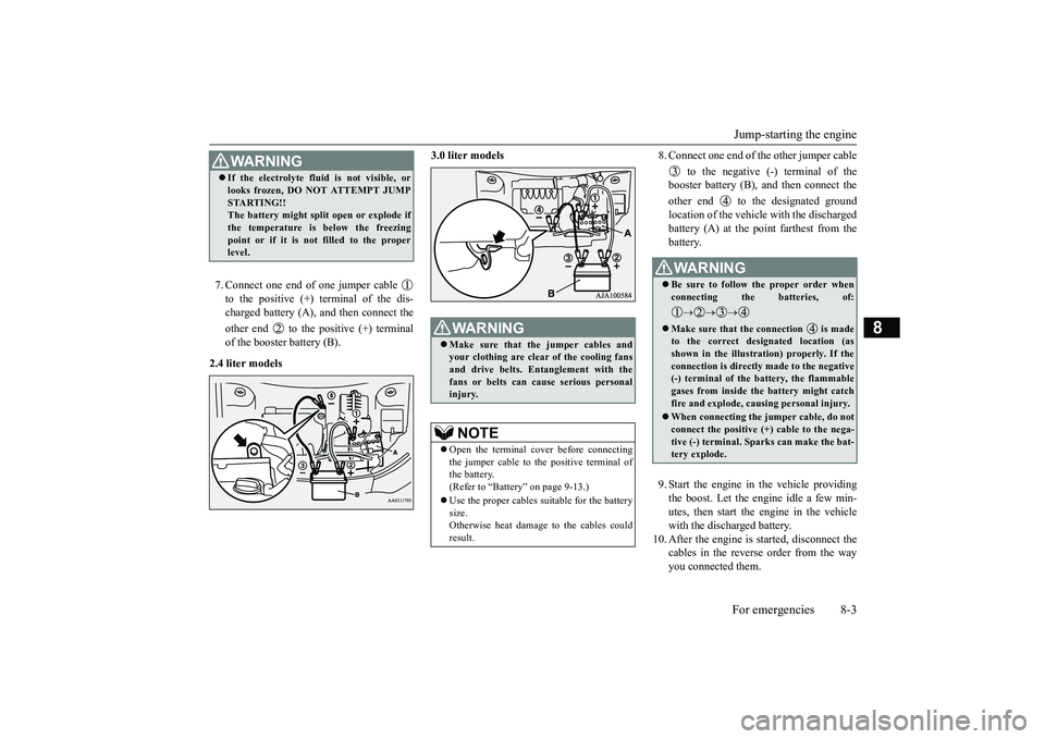
7. Connect one end of one jumper cable to the positive (+) terminal of the dis-charged battery (A),
and then connect the
other end to the positive (+) terminalof the booster battery (B).
2.4 liter models
3.0 liter models
8. Connect one end of the other jumper cable
to the negative (-) terminal of thebooster battery (B), a
nd then connect the
other end to the designated groundlocation of the vehicl
e with the discharged
battery (A) at the point farthest from thebattery.9. Start the engine in the vehicle providingthe boost. Let the engine idle a few min-utes, then start the engine in the vehiclewith the discharged battery.
10. After the engine is
started, disconnect the
cables in the reverse order from the wayyou connected them.
WA R N I N GIf the electrolyte flui
d is not visible, or
looks frozen, DO NOT ATTEMPT JUMPSTARTING!!The battery might split open or explode ifthe temperature is below the freezingpoint or if it is not filled to the properlevel.
WA R N I N GMake sure that the jumper cables andyour clothing are clear of the cooling fansand drive belts. Entanglement with thefans or belts can ca
use serious personal
injury.NOTE
Open the terminal cover before connectingthe jumper cable to the positive terminal ofthe battery.(Refer to “Battery” on page 9-13.)Use the proper cables suitable for the batterysize.Otherwise heat damage
to the cables could
result.
WA R N I N GBe sure to follow the proper order whenconnecting the batteries, of:
Make sure that the connection is madeto the correct designated location (asshown in the illustration) properly. If theconnection is directly made to the negative(-) terminal of the battery, the flammablegases from inside the battery might catchfire and explode, caus
ing personal injury.
When connecting the jumper cable, do notconnect the positive (+) cable to the nega-tive (-) terminal. Sparks can make the bat-tery explode.
BK0249100US.book 3 ページ 2017年5月10日 水曜日 午前8時49分