2018 MITSUBISHI OUTLANDER III USB
[x] Cancel search: USBPage 4 of 441
![MITSUBISHI OUTLANDER III 2018 Owners Manual Instruments and controls
Overview 1-2
1
Audio (if so equipped)[Refer to the separate owner’s manual.]Multi Around Monitor (if so equipped) P.5-144
Hazard warning flasher switch P.5-218
Electric rear MITSUBISHI OUTLANDER III 2018 Owners Manual Instruments and controls
Overview 1-2
1
Audio (if so equipped)[Refer to the separate owner’s manual.]Multi Around Monitor (if so equipped) P.5-144
Hazard warning flasher switch P.5-218
Electric rear](/manual-img/19/58144/w960_58144-3.png)
Instruments and controls
Overview 1-2
1
Audio (if so equipped)[Refer to the separate owner’s manual.]Multi Around Monitor (if so equipped) P.5-144
Hazard warning flasher switch P.5-218
Electric rear window defogger switch P.5-225Wiper deicer switch (if so equipped) P.5-224Fuel tank filler door release leverP. 3 - 3
Air conditioner P.7-5Hood release leverP. 9 - 3
Floor console box P.5-240Arm rest12 V power outlet P.5-230USB input terminal P.5-227
Cup holder P.5-242
12 V power outlet P.5-230
Power liftgate main switch (if so equipped) P.5-40
Key slot (if so equipped)
Passenger’s ventsP. 7 - 2
Passenger’s airbag off indicator P.4-40
Front passenger seat belt warning light P.4-23
Heated steering wheel switch (if so equipped)P.5-226
Blind Spot Warning (BSW) switch (if so equipped) P.5-126
Camera switch (if so equipped) P.5-148
BK0249100US.book 2 ページ 2017年5月10日 水曜日 午前8時49分
Page 83 of 441

5
Features and controlsInformation screen display (Vehicle equipped with the mul
ti information display - Type 1)
.................................................................................................. 5-206Combination headlights and dimmer switch ............................... 5-207Headlight leveling switch (if so equipped) .................................. 5-216Turn signal lever .......................................................................... 5-217Hazard warning flasher switch .................................................... 5-218ECO mode switch ........................................................................ 5-218Front fog light switch (if so equipped) ......................................... 5-218Wiper and washer switch ............................................................ 5-219Wiper deicer switch (if so equipped)............................................ 5-224Electric rear window def
ogger switch ......
...........
...........
............. 5-225
Heated steering wheel switch (if so equipped)............................. 5-226Horn switch ................................................................................. 5-227Link System ................................................................................. 5-227USB input terminal ...................................................................... 5-227Sun visors .................................................................................... 5-22912 V power outlets ...................................................................... 5-230HomeLink
® Wireless Control System (if so equipped) ............... 5-231
Interior lights ............................................................................... 5-236Storage spaces ............................................................................. 5-239Cup holders ................................................................................. 5-242Bottle holders .............................................................................. 5-243Cargo area cover (if so equipped) ............................................... 5-244Assist grips .................................................................................. 5-246Coat hooks ................................................................................... 5-246Luggage hooks ............................................................................ 5-246BK0249100US.book 2 ページ 2017年5月10日 水曜日 午前8時49分
Page 294 of 441

Combination headlights and dimmer switch
Features and controls 5-213
5
The sensitivity of the sensor can be temporar-ily lowering in the following ways.1. Park your vehicle in
a safe place and the
ignition switch is turned to the “OFF” or“LOCK” position or the operation modeis put in OFF.2. Press the automatic high beam systemswitch more than 15 times within 5 sec-onds after operation mode is turned on.
• A vehicle in front
or oncoming vehicle is
hindered by any object such as continuousbends, elevated median
/island, traffic signs,
roadside trees.• Your vehicle passes
an oncoming vehicle
suddenly on a bend with poor visibility.• Another vehicle crosse
s ahead of your vehi-
cle.
The headlights may remain at low beam (orbe switched from high beam to low beam)when a reflective object (e.g. street light,traffic signal, notic
eboard and signboard)
reflects light. Any of the following
factors may influence
the headlight beam switching timing:• How brightly the exteri
or lights of a vehicle
in front or oncoming
vehicle il
luminate.
• Movement or direction of a vehicle in frontor oncoming vehicle.• Only right or left exte
rior light of a vehicle
in front or oncoming
vehicle is illuminat-
ing.• A vehicle in front or
oncoming vehicle is a
motorcycle.• Road conditions (gradient, bends and roadsurface).• The number of occupants and luggage load.The automatic high beam system recognisesenvironmental conditi
ons by sensing a light
source ahead of your vehicle. Therefore, youmay feel like someth
ing is not quite right
when the headlight beams are switched auto-matically.NOTE
The system may not de
tect a light vehicle
such as a bicycle.The system may not detect an ambientbrightness precisely. Th
is causes the traffic
to be dazzled by high beam or the low beamto be maintained. In such cases, you shouldswitch the headlight beams manually.• In bad weather (heavy rain, fog, snow orsandstorm).• The windshield is
dirty or fogged up.
• The windshield is cracked or broken.• The sensor is deformed or dirty.• A light, which is similar to the headlights ortail lights, is shin
ing around your vehicle.
• A vehicle in front
or oncoming vehicle is
driven without lights,
the exterior lights are
dirty or discoloured, or the direction of theheadlight beams is adjusted improperly. • It becomes dark and bright suddenly andcontinuously around your vehicle.• Your vehicle is driv
en on uneven surfaces.
• Your vehicle is driven on a winding road.• A reflective object su
ch as a noticeboard or
a mirror reflects a light ahead of your vehi-cle.• When lights of the vehi
cle in front or head-
lights of an oncoming ve
hicle blend into the
other lights.• The rear end of a vehicle in front (such as acontainer truck) re
flect a strong light.
• Your vehicle's headligh
t is broken or dirty.
NOTE
• Your vehicle is inclined
due to a flat tire or
towing.• The warning display appears.(Refer to “System problem warning” onpage 5-214.)good usage conditions: • Do not attempt to disassemble the sensor.• Do not affix a sticke
r or label on the wind-
shield near the sensor.• Avoid overload.• Do not modify your vehicle.• When the windshield is
replaced, use the
Mitsubishi Motors genuine parts.
To adjust the sensitivity of the sensor
NOTE
BK0249100US.book 213 ページ 2017年5月10日 水曜日 午前8時49分
Page 308 of 441

Horn switch
Features and controls 5-227
5
N00523801195
To honk the horn, press around the “ ” markon the steering wheel.
N00563701183
The Link System takes control of the devicesconnected via the USB i
nput terminal or the
Bluetooth
® device; the system allows the
connected device to be operated by using theswitches in the vehicl
e or voice commands.
For details on how to operate, refer to “USBinput terminal” on page 5-227 and the sepa-rate owner’s manual.Bluetooth
® is a registered trademark of
BLUETOOTH SIG, INC.
N00566701168
You can connect your USB memory device oriPod
* to play music files stored in the USB
memory device or iPod.This section explains how to connect andremove a USB memory device or iPod.Refer to the separate owner’s manual fordetails on the types of
connectable devices
and supported files, and how to play musicfiles.*: “iPod” is a registered trademark of AppleInc. in the United Stat
es and other countries.
N00566801156
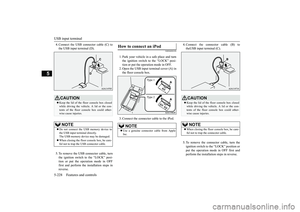
1. Park your vehicle in a safe place and turnthe ignition switch to the “LOCK” posi-tion or put the operation mode in OFF.
2. Open the USB input
terminal cover (A) in
the floor console box.3. Connect a commercia
lly available USB
connector cable (C) to the USB memorydevice (B).
Horn switch Link System
USB input terminal How to connect a USB memory device
Ty p e 1Ty p e 2
BK0249100US.book 227 ページ 2017年5月10日 水曜日 午前8時49分
Page 309 of 441

USB input terminal5-228 Features and controls
5
4. Connect the USB connector cable (C) tothe USB input terminal (D).5. To remove the USB connector cable, turnthe ignition switch to the “LOCK” posi-tion or put the operation mode in OFFfirst and perform the installation steps inreverse.
N00566901199
1. Park your vehicle in
a safe place and turn
the ignition switch to the “LOCK” posi-tion or put the operation mode in OFF.2. Open the USB input terminal cover (A) inthe floor console box.3. Connect the connector cable to the iPod.
4. Connect the connector cable (B) totheUSB input terminal (C).5. To remove the connect
or cable, turn the
ignition switch to the “LOCK” position orput the operation mode in OFF first andperform the installation steps in reverse.
CAUTIONKeep the lid of the floor console box closedwhile driving the vehicle. A lid or the con-tents of the floor console box could other-wise cause injuries.NOTE
Do not connect the US
B memory device to
the USB input term
inal directly.
The USB memory devi
ce may be damaged.
When closing the floor
console box, be care-
ful not to trap the USB connector cable.
How to connect an iPod
NOTE
Use a genuine connector
cable from Apple
Inc.
Ty p e 1Ty p e 2
CAUTIONKeep the lid of the floor console box closedwhile driving the vehicle. A lid or the con-tents of the floor console box could other-wise cause injuries.NOTE
When closing the floor
console box, be care-
ful not to trap the connector cable.
BK0249100US.book 228 ページ 2017年5月10日 水曜日 午前8時49分
Page 321 of 441

Storage spaces5-240 Features and controls
5
There is a card holder on the inside of theglove compartment.
N00551601286
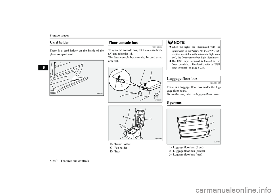
To open the console box, lift the release lever(A) and raise the lid.The floor console box can also be used as anarm rest.
N00552301075
There is a luggage floor box under the lug-gage floor board.To use the box, raise the luggage floor board.
Card holder
Floor console box B- Tissue holderC- Pen holderD- Tray
NOTE
When the lights are illuminated with thelight switch in the “ ”, “ ”, or “AUTO”
automatic light con-
trol), the floor consol
e box light illuminates.
The USB input terminal is located in thefloor console box. For de
tails, refer to “USB
input terminal” on page 5-227.
Luggage floor box 5 persons 1- Luggage floor box (front)2- Luggage floor box (center)3- Luggage floor box (rear)
BK0249100US.book 240 ページ 2017年5月10日 水曜日 午前8時49分
Page 440 of 441

Alphabetical index
12-5
12
5-57Wheel lock
............................
5-24
, 5-65
Stop lights
Bulb capacity
.................................
9-32
Storage spaces
..................................
5-239
Sun visors
........................................
5-229
Sunglasses holder
.............................
5-242
Sunroof
..............................................
5-51
Super-all wheel control (S-AWC)
S-AWC drive mode display
.............
5-87
S-AWC drive mode-selector
............
5-86
S-AWC operation display
................
5-87
Supplemental Re
straint System
............
4-35
How the Supplemental Restraint Systemworks
..........................................
4-38
Maintenance service
........................
4-50
T
Tail light
Bulb capacity
.................................
9-32
Tank capacity
.....................................
11-7
Theft-alarm system
.............................
5-46
Timing belt
........................................
9-25
Tire
...................................................
9-15
Inflation pressure
............................
9-19
Maintenance
...................................
9-20
Quality grading
...............................
10-2
Replacing tires and wheels
...............
9-19
Rotation
.........................................
9-20
Size (tire and wheel)
.......................
11-7
Snow tires
.....................................
9-21
Tire and loading information placard 11-3Tire chains
.....................................
9-22
To change a tire
................................
8-6
Tread wear indicator
.......................
9-20
Tire pressure monitoring system
.........
5-137
Tools
...................................................
8-6
Storage
............................................
8-5
Towing
..............................................
8-14
Trailer towing
....................................
6-11
Transfer oil
................................
9-12
, 11-7
Turn signal light
Indicators
.....................................
5-202
Lever
...........................................
5-217
U
USB input terminal
............................
5-227
How to connect a USB memory device
....
5-227How to connect an iPod
.................
5-228
V
Vanity mirror
....................................
5-229
Vanity mirror lights
Bulb capacity
.................................
9-33
Vehicle care precautions
.....................
9-39
Vehicle dimensions
............................
11-4
Vehicle labeling
..................................
11-2
Vehicle preparation before driving
..........
6-4
Vehicle weights
..................................
11-5
Vents
...................................................
7-2
W
Warning lights
..................................
5-203
Washer
Fluid
.....................................
9-12
, 11-7
Rear window washer
.....................
5-223
Switch
.........................................
5-223
Washing
.............................................
9-41
Waxing
..............................................
9-42
Weights
.............................................
11-5
Wheel
Covers
...........................................
8-13
Specification
..................................
11-7
Wiper
Rear window wiper
.......................
5-223
Switch
.........................................
5-219
Wiper blades
..................................
9-22
Wiper deicer switch
..........................
5-224
BK0249100US.book 5 ページ 2017年5月10日 水曜日 午前8時49分