2018 MITSUBISHI OUTLANDER III steering
[x] Cancel search: steeringPage 282 of 441
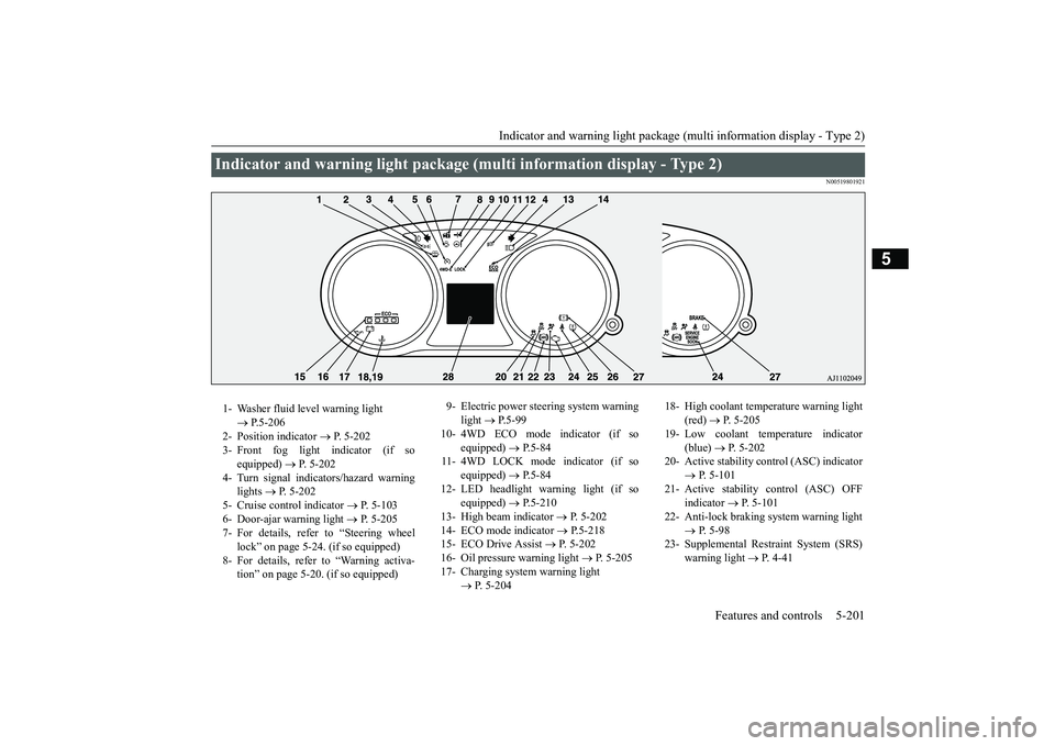
Indicator and warning light package (multi information display - Type 2)
Features and controls 5-201
5
N00519801921
Indicator and warning light package (mu
lti information display - Type 2)
1- Washer fluid level warning light
P.5-206
2- Position indicator
P. 5-202
3- Front fog light indicator (if so
equipped)
P. 5-202
4- Turn signal indicators/hazard warning
lights
P. 5-202
5- Cruise control indicator
P. 5-103
6- Door-ajar warning light
P. 5-205
7- For details, refer to “Steering wheel
lock” on page 5-24. (if so equipped)
8- For details, refer to “Warning activa-
tion” on page 5-20. (if so equipped)
9- Electric power steering system warning
light
P.5-99
10- 4WD ECO mode indicator (if so
equipped)
P.5-84
11- 4WD LOCK mode indicator (if so
equipped)
P.5-84
12- LED headlight warning light (if so
equipped)
P.5-210
13- High beam indicator
P. 5-202
14- ECO mode indicator
P.5-218
15- ECO Drive Assist
P. 5-202
16- Oil pressure warning light
P. 5-205
17- Charging system warning light
P. 5-204
18- High coolant temperature warning light
(red)
P. 5-205
19- Low coolant temp
erature indicator
(blue)
P. 5-202
20- Active stability control (ASC) indicator
P. 5-101
21- Active stability control (ASC) OFF
indicator
P. 5-101
22- Anti-lock braking system warning light
P. 5-98
23- Supplemental Restra
int System (SRS)
warning light
P. 4 - 4 1
BK0249100US.book 201 ページ 2017年5月10日 水曜日 午前8時49分
Page 298 of 441
Turn signal lever
Features and controls 5-217
5
N00522601590
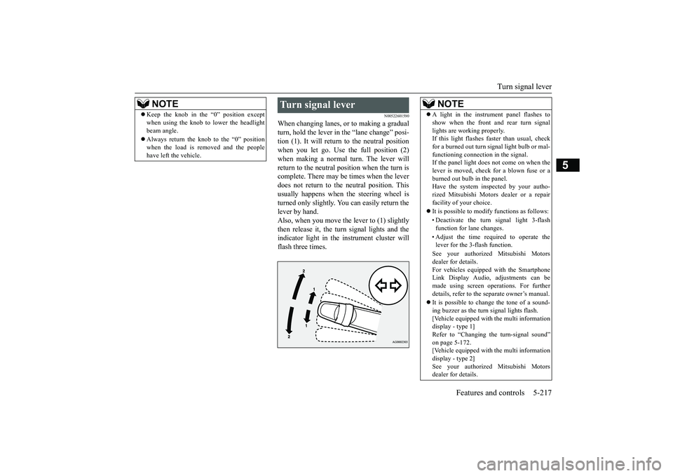
When changing lanes, or
to making a gradual
turn, hold the lever in the “lane change” posi-tion (1). It will return
to the neutral position
when you let go. Use the full position (2)when making a normal turn. The lever willreturn to the neutral position when the turn iscomplete. There may be times when the leverdoes not return to the neutral position. Thisusually happens when the steering wheel isturned only slightly. You
can easily return the
lever by hand.Also, when you move the lever to (1) slightlythen release it, the turn signal lights and theindicator light in the instrument cluster willflash three times.
Keep the knob in the “0” position exceptwhen using the knob to lower the headlightbeam angle.Always return the knob to the “0” positionwhen the load is removed and the peoplehave left
the vehicle.
NOTE
Turn signal lever
NOTE
A light in the instrument panel flashes toshow when the front and rear turn signallights are working properly.If this light flashes fa
ster than usual, check
for a burned out turn signal light bulb or mal-functioning connection in the signal.If the panel light does not come on when thelever is moved, check for a blown fuse or aburned out bulb in the panel.Have the system inspected by your autho-rized Mitsubishi Motors dealer or a repairfacility of your choice.It is possible to modi
fy functions as follows:
• Deactivate the turn signal light 3-flashfunction for lane changes.• Adjust the time required to operate thelever for the 3-flash function.See your authorized Mitsubishi Motorsdealer for details.For vehicles equipped with the SmartphoneLink Display Audio, adjustments can bemade using screen ope
rations. For further
details, refer to the
separate owner’s manual.
It is possible to change the tone of a sound-ing buzzer as the turn signal lights flash.[Vehicle equipped with the multi informationdisplay - type 1]Refer to “Changing the turn-signal sound”on page 5-172.[Vehicle equipped with the multi informationdisplay - type 2]See your authorized Mitsubishi Motorsdealer for details.
BK0249100US.book 217 ページ 2017年5月10日 水曜日 午前8時49分
Page 307 of 441
Heated steering wheel sw
itch (if so equipped)
5-226 Features and controls
5
N00589100032
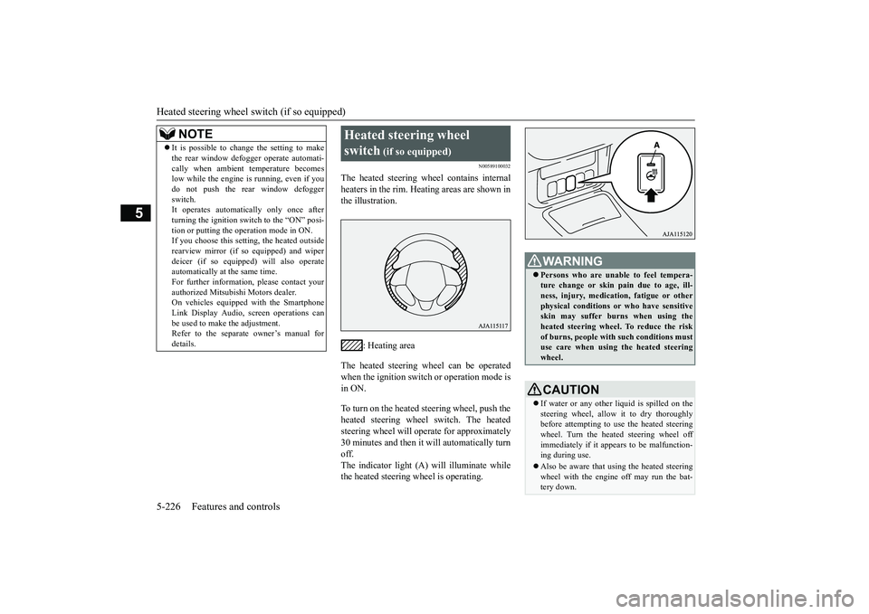
The heated steering wheel contains internalheaters in the rim. Heating areas are shown inthe illustration.
: Heating area
The heated steering wheel can be operatedwhen the ignition switch or operation mode isin ON.To turn on the heated steering wheel, push theheated steering wheel switch. The heatedsteering wheel will ope
rate for approximately
30 minutes and then it
will automatically turn
off.The indicator light (A) will illuminate whilethe heated steering wheel is operating.
It is possible to change the setting to makethe rear window def
ogger operate automati-
cally when ambient temperature becomeslow while the engine is running, even if youdo not push the rear window defoggerswitch.It operates automatica
lly only once after
turning the ignition switch to the “ON” posi-tion or putting the ope
ration mode in ON.
If you choose this setti
ng, the heated outside
rearview mirror (if so
equipped) and wiper
deicer (if so equippe
d) will also operate
automatically at the same time.For further information, please contact yourauthorized Mitsubishi Motors dealer.On vehicles equippe
d with the Smartphone
Link Display Audio, sc
reen operations can
be used to make the adjustment.Refer to the separate
owner’s manual for
details.NOTE
Heated steering wheel switch
(if so equipped)
Persons who are unable
to feel tempera-
ture change or skin
pain due to age, ill-
ness, injury, medicati
on, fatigue or other
physical conditions or
who have sensitive
skin may suffer burns when using theheated steering wheel. To reduce the riskof burns, people with such conditions mustuse care when using the heated steeringwheel.CAUTIONIf water or any other li
quid is spilled on the
steering wheel, allow it to dry thoroughlybefore attempting to use the heated steeringwheel. Turn the heated steering wheel offimmediately if it appe
ars to be malfunction-
ing during use.Also be aware that us
ing the heated steering
wheel with the engine off may run the bat-tery down.
BK0249100US.book 226 ページ 2017年5月10日 水曜日 午前8時49分
Page 308 of 441

Horn switch
Features and controls 5-227
5
N00523801195
To honk the horn, press around the “ ” markon the steering wheel.
N00563701183
The Link System takes control of the devicesconnected via the USB i
nput terminal or the
Bluetooth
® device; the system allows the
connected device to be operated by using theswitches in the vehicl
e or voice commands.
For details on how to operate, refer to “USBinput terminal” on page 5-227 and the sepa-rate owner’s manual.Bluetooth
® is a registered trademark of
BLUETOOTH SIG, INC.
N00566701168
You can connect your USB memory device oriPod
* to play music files stored in the USB
memory device or iPod.This section explains how to connect andremove a USB memory device or iPod.Refer to the separate owner’s manual fordetails on the types of
connectable devices
and supported files, and how to play musicfiles.*: “iPod” is a registered trademark of AppleInc. in the United Stat
es and other countries.
N00566801156
1. Park your vehicle in a safe place and turnthe ignition switch to the “LOCK” posi-tion or put the operation mode in OFF.
2. Open the USB input
terminal cover (A) in
the floor console box.3. Connect a commercia
lly available USB
connector cable (C) to the USB memorydevice (B).
Horn switch Link System
USB input terminal How to connect a USB memory device
Ty p e 1Ty p e 2
BK0249100US.book 227 ページ 2017年5月10日 水曜日 午前8時49分
Page 333 of 441

Vehicle preparation before driving6-4 Driving safety
6
N00629001709
For a safer and more enjoyable trip, alwayscheck for the following:Before starting the vehicle, make certainthat you and all passengers are seated andwearing their seat
belts properly (with
children in the rear seat, in appropriaterestraints), and that all the doors and theliftgate are locked.
Move the driver’s seat as far backward aspossible, while keeping good visibility,and good control of the steering wheel,brakes, accelerator, and controls. Checkthe instrument panel indicators and multi-information display
for any possible prob-
lem.Similarly, the front
passenger seat should
also be moved as fa
r back as possible.
Make sure that infants and small childrenare properly restrained in accordance withall laws and
regulations.
Check these by selecting the defroster mode,and set the blower swit
ch on high. You should
be able to feel the air blowing against thewindshield. Refer to “Defrosti
ng or defogging (wind-
shield, door windows)” on page 7-12Check all the tires for heavy tread wear oruneven wear patterns. Look for stones, nails,glass, or other objects
stuck in the tread. Look
for any tread cuts or
sidewall cracks. Check
the wheel nuts for tightness, and the tires(including spare tire) for proper pressure.
Replace your tires before they are heavilyworn out.As your vehicle is equi
pped with a tire pres-
sure monitoring system, there is a risk ofdamage to the tire inflation pressure sensorswhen the tire is replaced on the rim. Tirereplacement should, onl
y, be performed by an
authorized Mitsubishi Motors dealer.Have someone watch wh
ile you turn all the
exterior lights on and off. Also check the turnsignal indicators and hi
gh-beam indicators on
the instrument panel.Check the ground under the vehicle afterparking overnight, for
fuel, water, oil, or
other leaks. Make sure
all the fluid levels are
correct. Also, if you
can smell fuel, you need
to find out why imme
diately and have it
fixed.
N00629201134
Even this vehicle’s sa
fety equipment, and
your safest driving, ca
nnot guarantee that you
can avoid an accident or injury. However, if
Vehicle preparation before driving Seat belts and seats
Defrosters Tires
Lights Fluid leaks Safe driving techniques
BK0249100US.book 4 ページ 2017年5月10日 水曜日 午前8時49分
Page 335 of 441
Parking6-6 Driving safety
6
On snowy roads, ice can form on the brakingsystem, making the brakes less effective.While driving in such conditions, pay closeattention to surrounding
vehicles and to the
condition of the road surface. From time totime, lightly depress the brake pedal andcheck how effective the brakes are.It is important to take
advantage of the engine
braking by downshifting while driving onsteep downhill roads in order to prevent thebrakes from overheating.
N00629601385
When parking on a hill, set the parking brake,and turn the front wheels toward the curb on adownhill, or away from
the curb on an uphill.
If necessary, apply chocks to the wheels.Be sure that the parki
ng brake is firmly set
when parked and that the selector lever is inthe “P” (PARK) position.
When parking on a hill, it is important to setthe parking brake befo
re moving the selector
lever to the “P” (PARK) position. This pre-vents loading the parking brake against thetransaxle. When this ha
ppens, it is difficult to
move the selector lever out of the “P”Never leave the engine running while youtake a short nap or rest. Also, never leave theengine running in a closed or poorly venti-lated place.Your front bumper can be damaged if youscrape it over curbs or parking stop blocks.Be careful when traveling up or down steepslopes where your bumper can scrape theroad.
Always carry the key and lock all doors andthe liftgate when leaving the vehicle unat-tended.Always try to park your vehicle in a well litarea.Move effort could be required to turn thesteering wheel.Refer to “Electric power steering system(EPS)” on page 5-99.
N00629901434
It is very important to know how muchweight your vehicle can carry. This weight iscalled the vehicle ca
pacity weight and
includes the weight of
all occupants, cargo
(including the roof load), non-factory-
When driving in cold weather When driving downhill Parking Parking on a hill
Parking with the engine run-ning
WA R N I N GLeaving the engine ru
nning risks injury or
death from accidentally moving the selec-tor lever or the accumulation of toxicexhaust fumes in the passenger compart-ment.
Where you park
WA R N I N GDo not park your vehicle in areas wherecombustible materials
such as dry grass or
leaves can come in contact with a hotexhaust, since a fire could occur.
When leaving the vehicle Do not keep the steering wheel fully turned for a long time Loading information
BK0249100US.book 6 ページ 2017年5月10日 水曜日 午前8時49分
Page 336 of 441
Loading informationDriving safety 6-7
6
installed options, and
the tongue weight of
the trailer, if any, being towed. The tire andloading information placard located on thedriver’s door sill of your vehicle will showhow much weight it may properly carry.It is important to famil
iarize yourself with the
following terms before loading your vehicle:Vehicle maximum load on the tire: loadon an individual tire that is determined bydistributing to each axle its share of themaximum loaded vehicle weight anddividing by two.Vehicle normal load on the tire: load on anindividual tire that is determined by dis-tributing to each axle its share of the curbweight, accessory weight, and normaloccupant weight and dividing by two.Maximum loaded vehicle weight: the sumof -(a) Curb weight;(b) Accessory weight;(c) Vehicle capacity weight; and(d) Production options weight.
Curb weight: the weight of a motor vehi-cle with standard equipment including themaximum capacity of
fuel, oil, and cool-
ant.Accessory weight: the combined weight(in excess of those st
andard items which
may be replaced) of automatic transaxle,power steering, power brakes, power win-dows, power seats, radio, and heater, tothe extent that these items are available asfactory- installed equipment (whetherinstalled or not).Vehicle capacity weight: the rated cargoand luggage load plus 150 lbs (68 kg)*times the vehicle’s designated seatingcapacity.Production options weight: the combinedweight of those installed regular produc-tion options weighing over 5 lbs (2.3 kg)in excess of those standard items whichthey replace, not prev
iously considered in
curb weight or accessory weight, includ-ing heavy duty brakes,
ride levelers, roof
rack, heavy duty battery, and special trim.Normal occupant weight: 150 lbs (68 kg)*times the number of
specified occupants
(3 in the case of your vehicle)Occupant distribution:
Occupant distribu-
tion within the passenger compartment (Inyour vehicle the distribution is 2 in front,1 in second row seat)
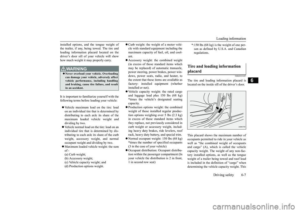
N00630101407
The tire and loading information placard islocated on the inside sill of the driver’s door.This placard shows the maximum number ofoccupants permitted to
ride in your vehicle as
well as “the combined
weight of occupants
and cargo” (A), which
is called the vehicle
capacity weight. The weight of any non-fac-tory installed options, as well as the tongueweight of a trailer being towed and roof loadis included in the defi
nition of “cargo” when
determining the vehicle
capacity weight. This
WA R N I N GNever overload your ve
hicle. Overloading
can damage your vehicl
e, adversely affect
vehicle performance, including handlingand braking, cause tire failure, and resultin an accident.
*:150 lbs (68 kg) is the weight of one per-son as defined by U.
S.A. and Canadian
regulations.
Tire and loading information placard
BK0249100US.book 7 ページ 2017年5月10日 水曜日 午前8時49分
Page 340 of 441
Trailer towing
Driving safety 6-11
6
N00630601112
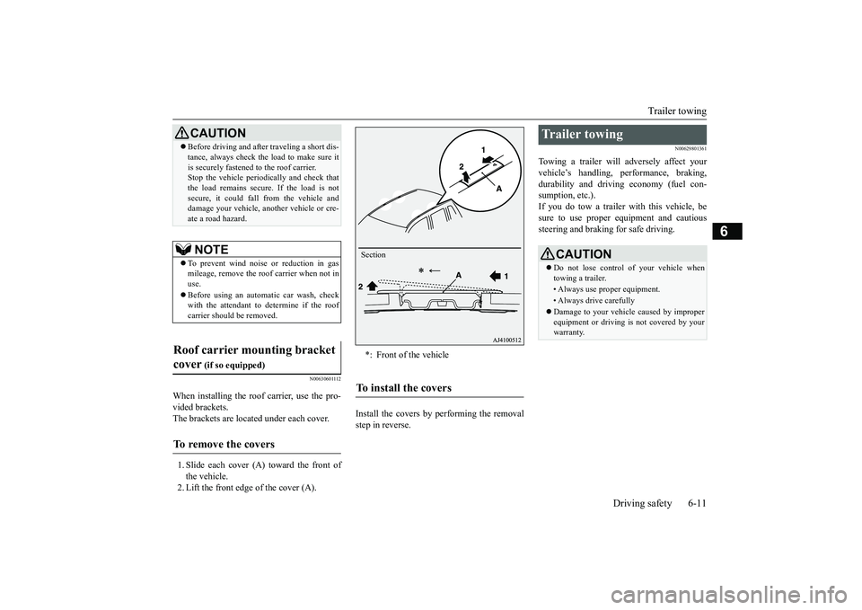
When installing the roof carrier, use the pro-vided brackets.The brackets are located under each cover.1. Slide each cover (A) toward the front ofthe vehicle.2. Lift the front edge of the cover (A).
Install the covers by performing the removalstep in reverse.
N00629801361
Towing a trailer will adversely affect yourvehicle’s handling, performance, braking,durability and driving economy (fuel con-sumption, etc.).If you do tow a trailer
with this vehicle, be
sure to use proper e
quipment and cautious
steering and braking for safe driving.
Before driving and after traveling a short dis-tance, always check the load to make sure itis securely fastened to the roof carrier.Stop the vehicle periodi
cally and check that
the load remains secure. If the load is notsecure, it could fall from the vehicle anddamage your vehicle,
another vehicle or cre-
ate a road hazard.NOTE
To prevent wind noise or reduction in gasmileage, remove the roof carrier when not inuse.Before using an automatic car wash, checkwith the attendant to determine if the roofcarrier should be removed.
Roof carrier mounting bracket cover
(if so equipped)
To remove the covers
CAUTION
*: Front of the vehicleTo install the covers
Section
Trailer towing
CAUTIONDo not lose control of your vehicle whentowing a trailer.• Always use proper equipment.• Always drive carefullyDamage to your vehicle caused by improperequipment or driving is not covered by yourwarranty.
BK0249100US.book 11 ページ 2017年5月10日 水曜日 午前8時49分