2018 MERCEDES-BENZ SLC ROADSTER wheel size
[x] Cancel search: wheel sizePage 21 of 298

Maximum load onatire (defini-
tion) ............................................... 279
Maximum loaded vehicle weight
(definition) .....................................2 79
Maximum permissible tire pres-
sure (definition) .............................2 79
Maximum tire load. ........................ 277
Maximum tire load( definition) ....... 279
MOExtended tires .......................... 262
Optional equipment weight (defi-
nition) ............................................ 280
Overview ........................................ 260
PSI (pounds per square inch) (def-
inition) ...........................................2 79
Replacing ....................................... 280
Service life ..................................... 261
Sidewall (definition) ....................... 279
Speed rating (definition) ................ 279
Storing ...........................................2 81
Structure and characteristics
(definition) ..................................... 278
Summer tires ................................. 262
Temperature .................................. 274
TIN (Tire Identification Number)
(definition) ..................................... 280
Tire bead( definition) ......................2 79
Tire pressure (definition) ................ 279
Tire pressure s(recommended). ..... 278
Tire size (data) ............................... 284
Tire size designation, load-bearing
capacity, speedr ating .................... 275
Tire tread ....................................... 261
Tire tread (definition) ..................... 279
Total loadl imit (definition) ............. 280
Traction ......................................... 274
Traction (definition) ....................... 280
Treadw ear..................................... 274
Uniform Tire Quality Grading
Standard s...................................... 273
Uniform Tire Quality Grading
Standard s(de finition) .................... 278
Wea rindicator (definition) ............. 280
Wheel and tire combination ........... 284
Wheel rim (definiti on) .................... 278
se
e Fla ttire
Tow-starting
Emergency engine starting ............ 258
Important safety notes .................. 256 Towin
gaway
Important safety guideline s........... 256
Installing the towing eye. ............... 256
Removing the towing eye. .............. 257
Transporting the vehicl e................ 258
With both axles on the ground ....... 257
With the reara xler aised ................ 257
Trafficr eports
see also Digital Operator's Man-
ua l.................................................. 211
Transmission
Selector lever ................................ 122
see Automati ctransmission
Transmissio nposition display ......... 122
Transporting the vehicle .................. 258
Trip computer (on-board com-
puter) .................................................. 166
Trip odometer
Calling up ....................................... 166
Resetting (on-board computer) ...... 167
Trunk
Emergency release .......................... 73
Important safety notes .................... 72
Locking separately. .......................... 73
Opening/closing (manuall yfrom
outside) ............................................ 73
Overview .......................................... 72
Trunk lid
Displa ymessage ............................ 200
Opening dimensions ...................... 295
Trunk partition
Displa ymessage ............................ 200
Generaln otes .................................. 79
Opening/closing .............................. 80
Turn signals
Displa ymessage ............................ 189
Switching on/off. ............................. 96
Two-wa yradio
Frequencie s................................... 288
Installation ..................................... 288
Transmission output( maximum) .... 288
Type identificatio nplate
see Vehicl eide ntification plate
U
Unlocking
Emergency unlocking ....................... 72
Index19
Page 23 of 298
Removingawheel.......................... 283
Storing ........................................... 281
Tightening torque ........................... 284
Wheel size/tire size ....................... 284
Win dscreen
Inserting and removing .................... 80
Preparing for installation .................. 80
see AIRGUIDE
Windows
see Sid ewindows
Windshield
Defrosting ...................................... 110
Windshiel dwasher fluid
see Windshield washers ystem
Windshiel dwasher system
Adding washerf luid ....................... 236
Important safety notes .................. 294
Windshiel dwipers
Displa ymessage ............................ 201
Problem (malfunction) ................... 103
Replacing the wipe rblade s............ 101
Switching on/off. .......................... 101
Winter driving
Important safety notes .................. 262
Slippery roads urfaces ................... 138
Snow chains .................................. 262
Winter operation
Overview ........................................ 262
Winter tires
M+S tire s....................................... 262
Wipe rblades
Cleaning ......................................... 241
Important safety notes .................. 101
Replacing ....................................... 101
Workshop
see Qualifie dspecialist workshop
Z
ZONE function
Switching on/off. .......................... 110
Index21
Page 55 of 298
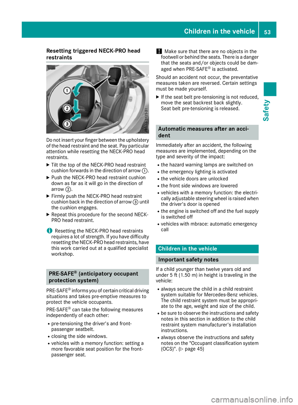
Resetting triggeredNECK-PRO head
restraints
Do not insert your finger between the upholstery of the headr estraint and the seat. Payp articular
attention whil eresetting the NECK-PROh ead
restraints.
XTilt the top of the NECK-PROh eadrestraint
cushio nforward sinthe direction of arrow :.
XPush the NECK-PROh eadrestraint cushion
dow nasfar as it will go in the direction of
arrow ;.
XFirmly push the NECK-PROh eadrestraint
cushio nbackint he direction of arrow =until
the cushio nengages.
XRepea tthis procedure for the second NECK-
PROh eadrestraint.
iResetting the NECK-PROh eadrestraints
requires alot of strength. If yo uhaved ifficulty
resetting the NECK-PROh eadrestraints, have
this work carrie doutataq uali fied specialist
workshop.
PRE-SAFE®(anticipatory occupant
protection system)
PRE-SAFE®informs yo uofcertain critical driving
situations and take spre-emptive measures to
protect the vehicl eoccupants.
PRE-SAFE
®can take the following measures
independentl yofeacho ther:
Rpre-tensioning the driver'sa nd front-
passenger seatbelt.
Rclosing the sid ewindows.
Rvehicles with amemory function: setting a
more favorabl eseatp osition for the front-
passenger seat.
!Make sure that there are no objects in the
footwell or behind the seats. There is adanger
that the seats and/or objects could be dam-
aged when PRE-SAFE
®is activated.
Should an accident not occur, the preventative
measures take nare reversed. Certai nsettings
mus tbem adey ourself.
XIf the seatb eltp re-tensioning is not reduced,
move the seatb ackrest back slightly.
Seatb eltp re-tensioning is released.
Automatic measures after an acci-
dent
Immediately afte ranaccident, the following
measures are implemented, depending on the
typ eand severity of the impact:
Rthe hazard warning lamps are switched on
Rthe emergency lighting is activated
Rthe vehicl edoors are unlocked
Rthe front sid ewindow sare lowered
Rvehicles with amemory function: the electri-
cally adjustabl esteering wheel is raised when
the driver'sd ooriso pened
Rthe engine is switched off and the fue lsuppl y
is switched off
Rvehicles with mbrace: automatic emergency
call
Childrenint he vehicle
Important safety notes
Ifac hild younger than twelve years olda nd
under 5ft(1.50 m) in height is traveling in the
vehicle:
Ralways secur ethe child in achild restraint
systems uitabl efor Mercedes-Benz vehicles.
The child restraint systemm ustbea ppropri-
ate to the age, weight and size of the child.
Rbe sure to observe the instructions and safety
notesint hissectio nina dditiontot he child
restraint systemm anufacturer's installation
instructions.
Ralways observe the instructions and safety
notesont he "Occupant classification system
(OCS)". (
Ypage 45)
Children in the vehicle53
Safety
Z
Page 63 of 298
When towing the vehicle with the rear axle
raised, observe the notes on ESP®
(Ypage 257).
If the å ESP®OFF warning lamp lights up
continuously, then ESP®is deactivated.
If the ÷ ESP®warning lamp and the å
ESP®OFF warning lamp are lit continuously,
ESP®is not available due to amalfunction.
Observe the information on warning lamps
(
Ypage 205) and display messages which may
be shown in the instrument cluster
(
Ypage 179).
iOnly use wheels with the recommended tire
sizes. Only then will ESP®function properly.
Characteristics of ESP®
General information
If the ÷ ESP®warning lamp goes out before
beginnin gthe journey, ESP®is automatically
active.
If ESP
®intervenes, the ÷ESP®warning lamp
flashes in the instrument cluster.
If ESP
®intervenes:
XDo not deactivat eESP®under any circum-
stances.
XOnly depress the accelerator pedal as far as
necessary when pulling away.
XAdapt your driving style to suit the prevailing
road and weather conditions.
ECO start/stop function
The ECO start/stop function switches the
engine off automatically when the vehicle stops
moving. The engine start sautomatically when
the driver wants to pull away again. ESP
®
remains in its previously selected status, e.g. if
ESP®was deactivated before the engine was
automatically switched off.
Activating/deactivating ESP®(except
Mercedes-AMG SLC 43)
Important safety notes
iObserve the "Important safety notes" sec-
tion (Ypage 56). You can select between the following states of
ESP
®:
RESP®is activated
RESP®is deactivated
GWARNING
If you deactivat eESP
®,ESP®no longer sta-
bilizes the vehicle. There is an increased risk
of skidding and an accident.
Only deactivat eESP
®in the situation sdescri-
bed in the following.
It may be best to deactivat eESP
®in the follow-
ing situations:
Rwhen using snow chains
Rin deep snow
Ron sand or gravel
Spinning the wheels results in acutting action
which provides better grip.
iActivate ESP®as soon as the situations
described above no longer apply. ESP®will
otherwise not be able to stabilize the vehicle if
the vehicle start stoskid or awheel start sto
spin.
!Avoid spinnin gthe driven wheels for an
extended period with ESP®deactivated. You
could otherwise damage the drivetrain.
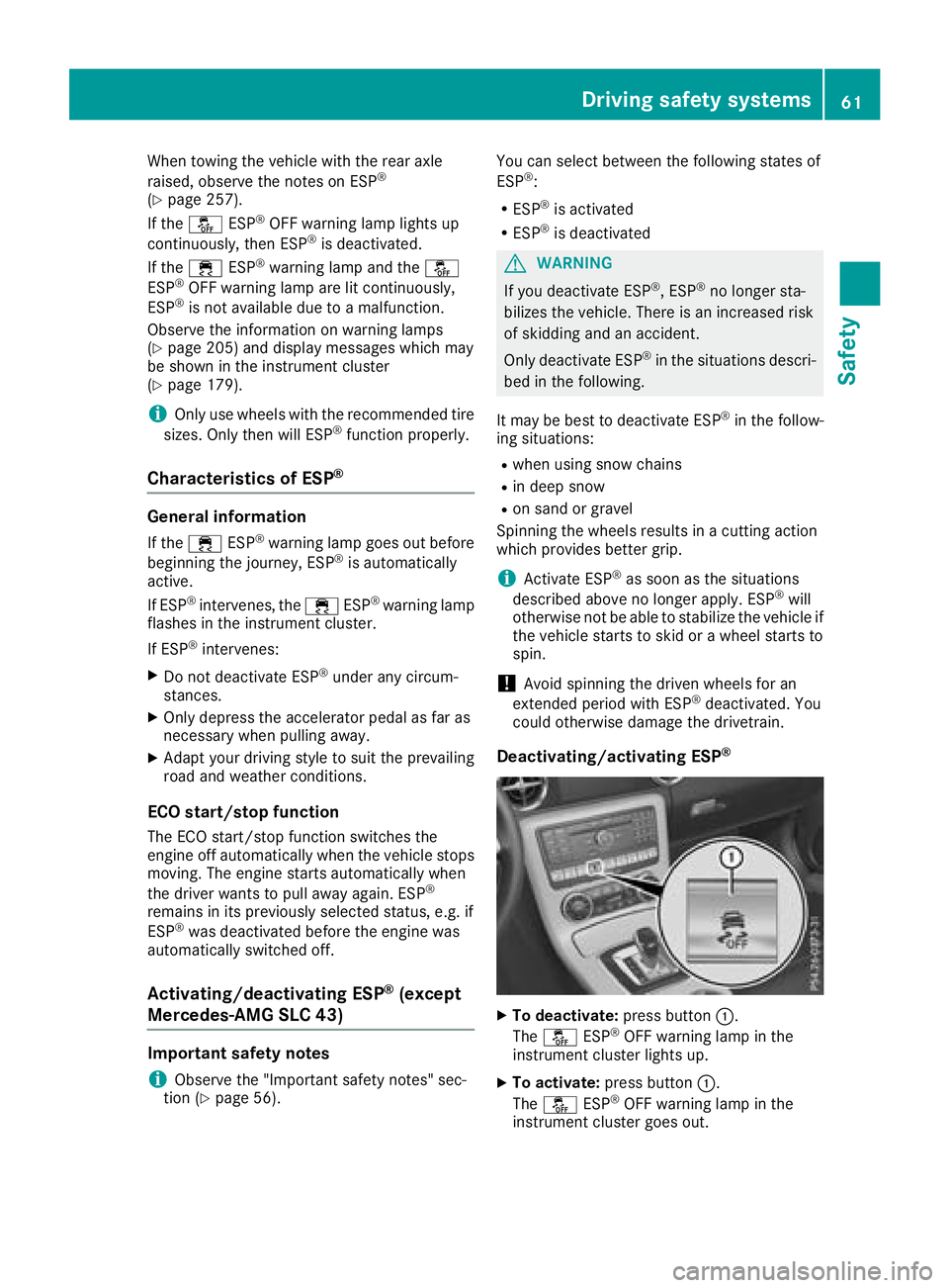
Deactivating/activating ESP®
XTo deactivate: press button:.
The å ESP®OFF warning lamp in the
instrument cluster lights up.
XTo activate: press button :.
The å ESP®OFF warning lamp in the
instrument cluster goes out.
Driving safety systems61
Safety
Z
Page 93 of 298
Exteriormirrors
Adjusting th eexterio rmirrors
GWARNING
You coul dlose control of your vehicle if you do
th ef ollowingw hile driving:
Radjust thedriver'ss eat,head restraint,
steering wheel or mirrors
Rfasten th eseat belt
Thereisar isk of an accident.
Adjust th edriver'ss eat,head restraint ,steer-
ing wheel and mirror and fasten your seat belt before starting th eengine.
GWARNING
The exteriorm irror on thefront-pa ssenger
side reduces th esizeoft heimage .Visible
object sare actually closer than they appear.
This mean sthaty ou coul dmisjudge th edis-
tance from road userst ravelin gbehind, e.g.
when changing lane .Thereisar isk of an acci-
dent.
For this reason,a lways makesure of the
actual distanc efromt heroad userst raveling
behindbyg lancingovery our shoulder.
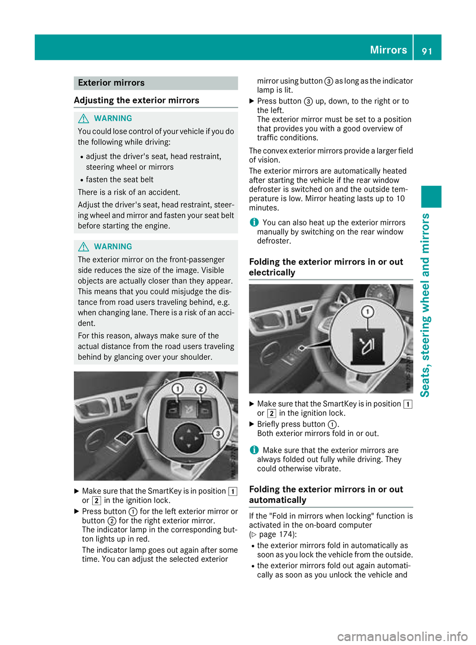
XMakes ure that th eSma rtKey is in position 1
or 2 in th eignition lock.
XPress button :for th eleft exteriorm irror or
button ;for th erigh texteriorm irror.
The indicator lamp in th ecorrespondingb ut-
to nl ightsupinr ed.
The indicator lamp goes out again after some time. You can adjust th eselecte dexterior mirror usingb
utton=as longast heindicator
lamp is lit.
XPress button =up, down,tot herigh tort o
th el eft.
The exteriorm irror must be set to aposition
that provide syou with agood overview of
traffic conditions.
The convex exteriorm irrorsprovide alarge rfield
of vision.
The exteriorm irrorsare automaticall yheated
after starting th evehicle if th erear window
defroster is switched on and th eoutside tem-
perature is low. Mirror heating lastsupto1 0
minutes.
iYou can also heat up th eexteriorm irrors
manually by switching on th erear window
defroster.
Foldin gthe exterio rmirror sinoro ut
electrically
XMakes ure that th eSma rtKey is in position 1
or 2 in th eignition lock.
XBriefly pres sbutton :.
Bot hexteriorm irrorsfold in or out.
iMakes ure that th eexteriorm irrorsare
always folded out fully while driving .They
coul dotherwise vibrate.
Foldin gthe exterio rmirror sinoro ut
automatically
If th e"Fol dinm irrorswhen locking" function is
activated in th eon-board computer
(
Ypage 174):
Rth ee xteriorm irrorsfold in automaticall yas
soon as you lockt hevehicle from th eoutside.
Rthee xteriorm irrorsfold out again automati-
cally as soon as you unlock th evehicle and
Mirrors91
Seats, steerin gwheel and mirrors
Z
Page 247 of 298
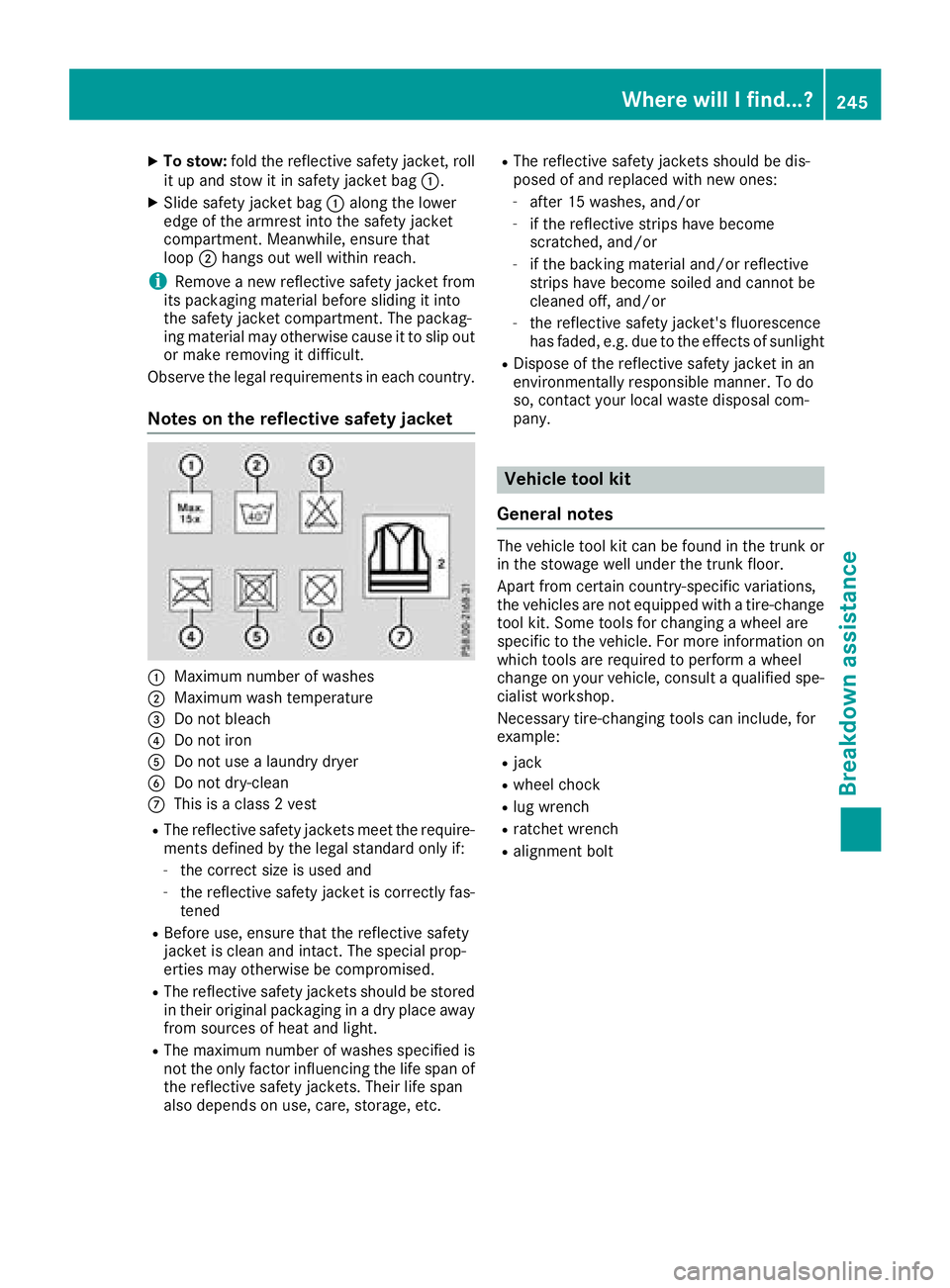
XTo stow:foldthe reflective safety jacket, roll
it up and stow it in safety jacke tbag :.
XSlide safety jacke tbag : along the lower
edge of the armresti nto the safety jacket
compartment. Meanwhile, ensure that
loop ;hangs outw ellw ithinr each.
iRemove anew reflective safety jacke tfrom
its packaging material before sliding it into
the safety jacke tcompartment. The packag-
ing material may otherwise cause it to slip out
or make removing it difficult.
Observ ethe legalr equirements in each country.
Notesont he reflective safety jacket
:Maximu mnumbe rofw ashes
;Maximu mwasht emperature
=Do not bleach
?Do not iron
ADo not us ealaundry dryer
BDo not dry-clean
CThi sisa class2vest
RThe reflective safety jackets meett he require-
ments define dbythe legals tandard onlyi f:
-the correct size is used and
-the reflective safety jacke tisc orrectl yfas-
tened
RBefore use, ensure thatt he reflective safety
jacke tisc lean and intact. The specia lprop-
erties mayo therwise be compromised.
RThe reflective safety jackets shoul dbestored
in thei roriginal packaging in adry place away
from sources of hea tand light.
RThe maximu mnumbe rofwashess pecified is
not the onlyf actor influencing the life spa nof
the reflective safety jackets. Their life span
also depends on use, care, storage, etc.
RThe reflective safety jackets shoul dbedis-
posed of and replaced with new ones:
-afte r15w ashes, and/or
-if the reflective strips have become
scratched ,and/or
-if the backing material and/or reflective
strips have become soile dand canno tbe
cleane doff, and/or
-the reflective safety jacket's fluorescence
hasf aded ,e.g.d ue to the effects of sunlight
RDispose of the reflective safety jacke tinan
environmentally responsibl emanner. To do
so, contact your local waste d
isposalc
om-
pany.
Vehicl etoolkit
General notes
The vehicl etool kit can be found in the trunk or
in the stowag ewellu nder the trunk floor.
Apart from certain country-specifi cvariations,
the vehicles are not equipped with atire-change
tool kit. Some tool sfor changing awheel are
specifi ctothe vehicle. For more informatio non
which tool sare required to performaw heel
change on your vehicle, consult aquali fied spe-
cialist workshop.
Necessary tire-changing tool scan include, for
example:
Rjack
Rwhee lchock
Rlugw rench
Rratchet wrench
Ralignment bolt
Where will Ifind...?245
Breakdo wn assis tance
Page 249 of 298
MOExtended tires (tires with run-flat
properties)
General notes
With MOExtended tires (tires with run flat char-
acteristics), you can continue to drive you rvehi-
cle even if there is atotal loss of pressure in one
or more tires. The affected tire must not show
any clearly visible damage.
You can recognize aMOExtended tire by the
MOExtended marking which appears on the
sidewal lofthe tire. You wil lfind this marking
next to the tire size designation, the load-bear-
ing capacity and the speedi ndex (
Ypage275).
MOExtended tires may only be use dinconjunc-
tion with an active tire pressure loss warning
system or with an active tire pressure monitor.
If ap ressure lossw arningmessagea ppears
in the multifunction display:
Robserve the instructions in the display mes-
sage s(Ypage1 96)
Rcheck the tire for damage
Rif driving on, observe the following notes
The driving distance possible in run-fla tmode is
approximately 50 mile s(80 km) when the vehi-
cle is partiall yladen and approximately 19 miles
(30 km) when the vehicleisf ullyladen.
In addition to the vehiclel oad, the driving dis-
tance possible depends upon:
Rvehicles peed
Rroad condition
Routside temperature
The driving distance possible in run-fla tmode
may be reduced by extreme driving conditions
or maneuvers, or it can be increased through a
moderate style of driving.
The driving distance possible in run-fla tmode is
counted from the moment the tire pressure loss
warning appears in the multifunction display.
You must not exceed amaximu mdesign speed
of 50 mph (80 km/h).
When replacing one or all tires, please observe
the following specifications for you rvehicle's
tires:
Rsize
Rtype and
Rthe "MOExtended "mark
If at ire has gone flat and cannot be replaced
with aMOExtended tire, astandard tire may be
use dasat emporary mea
sure. Make sure thatyou use the propers
ize and type (summer or
winter tire).
Vehicles equipped with MOExtended tires are
not equipped with aTIREFIT kit at the factory. It
is therefore recommendedt hat you additionally
equip you rvehiclew ithaTIREFIT kit if you mount
tires that do not feature run-fla tcharacteristics,
e.g. winter tires. ATIREFIT kit can be obtained
from aqualified specialist workshop, for exam-
ple.
Important safety notes
GWARNING
When driving in emergency mode, the driving
characteristics deteriorate, e.g. when corner-
ing, accelerating quickly and when braking.
There is arisk of an accident.
Do not exceed the stated maximu mspeed.
Avoid abrupt steering and driving maneuvers,
and driving over obstacles (curbs, potholes,
off-road). This appliesinp articulartoaladen
vehicle.
Stop driving in emergency mode if:
Ryou hearb anging noises.
Rthe vehicles tarts to shake.
Ryou see smoke and smell rubber.
RESP®is intervening constantly.
Rthere are tears in the sidewalls of the tire.
After driving in emergency mode, have the
wheelr ims checked at aqualified specialist
workshopw ith regard to their further use .The
defective tire must be replaced in every case.
TIREFIT kit
Important safety notes
TIREFIT is atire sealant.
You can use TIREFIT to seal puncture sofupto
0.16 in (4 mm) ,particularly those in the tire
tread. You can use TIREFIT at outside tempera-
tures downt oÒ4‡( Ò20 †).
Flat tire247
Breakdown assistance
Z
Page 263 of 298
Checkwheelsand tires for damag eatleast once
am onth .Checkw heelsa nd tires after driving
off-road or on roug hroads. Damaged wheels
can caus ealoss of tir epressure. Pay particular
attentio ntodamagesucha s:
Rcutsint hetires
Rpunctures inthet ires
Rtears inthet ires
Rbulges on tires
Rdeformatio norsevere corrosiononw heels
Regularly check thetiret read dept hand the
conditio nofthetread across th ewhole widthof
th et ire(
Ypage 261). Ifnecessary, tur nthe
frontw heelstof ull lockino rder to inspectt he
inner sideof thetires urface.
All wheelsm ust haveavalvec ap to protect the
valv eagainst dirtand moisture. Do no tmount
anythingo ntot he valv eother than th estandard
valv ecap or other valv ecaps approved by
Mercedes-Ben zfor your veh icle.Don otuse any
other valv ecaps or systems ,e.g.t irep ressure
monitorin gsystems.
Regularly check thepressureofa llth et ires par-
ticularly priortol ongt rips. Adjus tthe tirep res-
sure as necessary (
Ypage 263).
Observ ethe note sont heemergenc yspare
wheel (
Ypage 285).
The servic elife of tires depends, amon gother
things, on th efollowin gfactors:
Rdriv ing style
Rtirep ressure
Rdist ancecovered
Notes on tir etread
GWAR NING
In suff icient tir etread will reduce tir etraction.
The tir eisnol ongerabletodissipat ewater.
This mean stha tonw et road surfaces ,the risk
of hydroplaning increases, inparticular where
speedisn otadapted to suit th edriving con-
dit ions. Thereisar iskofa cciden t.
If th et irep ressureist oohigh or to olow, tires
may exhibit different leve lsof wear at differ-
entl ocations on th etiret read. Thus,y ou
should regularly check th etread dept hand
th ec onditio noft hetread across th eentire
widt hofa lltires.
Minimum tir etread depthf or:
RSummer tires: âin(3 mm)
RM+S tires: ãin(4 mm)
For safety reasons, replace th etires before
th el egally prescribe dlimit for th eminimum
tir et read depthisr eached.
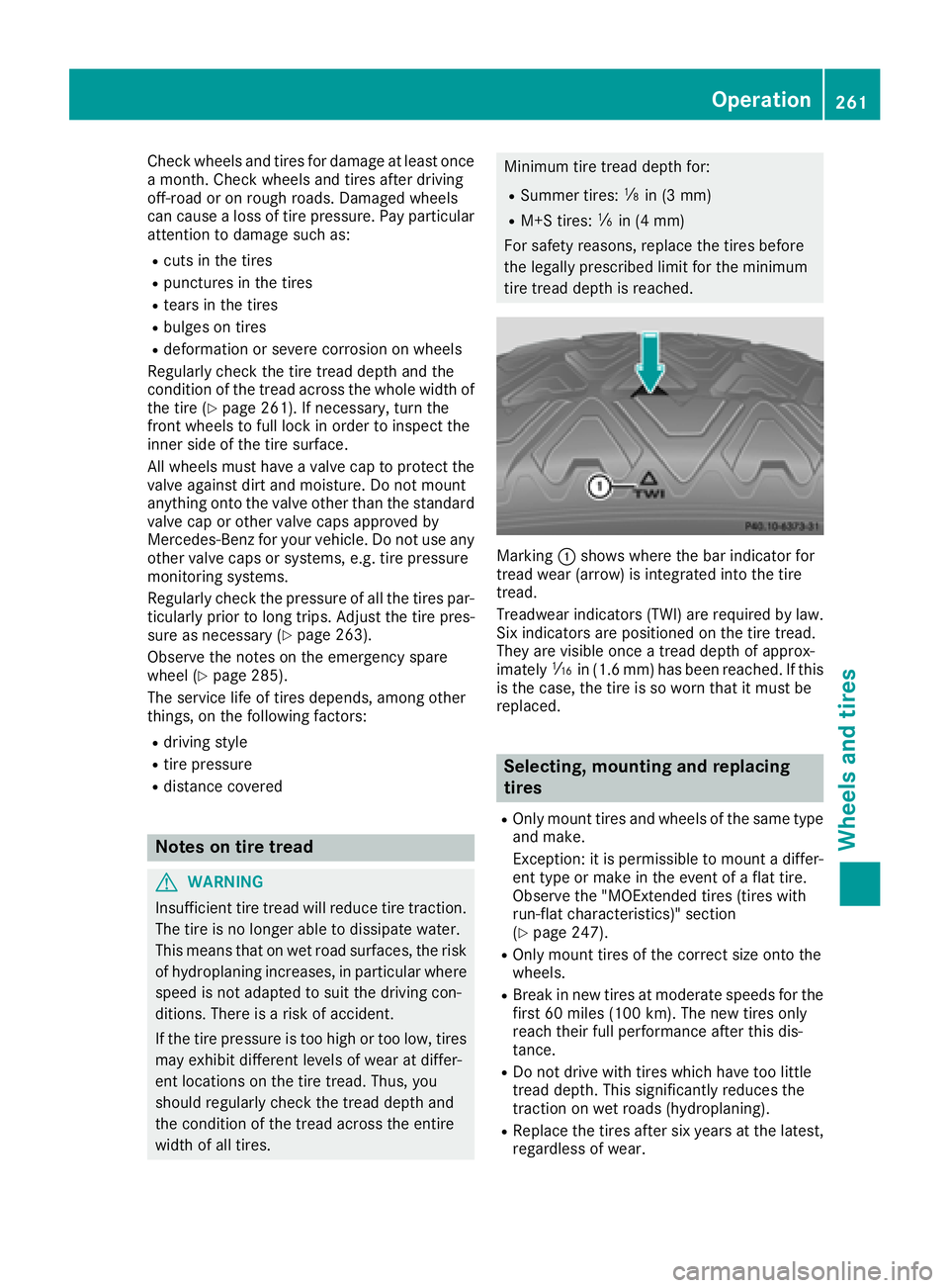
Marking:shows wheret hebar indicator for
tread wear (arrow) is integrate dintot he tire
tread.
Treadwear indicators (TWI)a re required by law.
Six indicators are positione donthetiret read.
They are vis ibleonce atread depthofa pprox-
imately áin (1. 6mm) has been reached. If this
is th ecase, th etireissow orn that it must be
replace d.
Selecting, mounting and replacing
tires
ROnly moun ttires and wheelsoft hesame type
and make.
Exception: itis permissible to moun tadiffer-
entt ype or mak eintheevent of aflat tire.
Observ ethe "MOExtended tires (tires with
run-flat characteristics)" section
(
Ypage 247).
ROnly moun ttires of th ecorrec tsizeo ntot he
wheels.
RBreak inne wt ires at moderat espeeds for the
first 60 mile s(10 0k m). The ne wtires only
reac htheirfull performance after this dis-
tance.
RDo no tdrivew itht ires whic hhave to olittle
tread depth. This significantly reduces the
traction on wet road s(hydroplaning).
RReplacet hetires after six years at th elatest,
regardless of wear.
Operation261
Wheels and tires
Z