2018 MERCEDES-BENZ SLC ROADSTER phone
[x] Cancel search: phonePage 228 of 298

XTo initiate an emergencycallm anually:
press cover :briefl ytoo pen.
XPress SOS button ;briefly.
The indicator lamp in SOS button ;flashes
unti lthe emergency cal lisconcluded.
XWait for avoice connectio ntothe Mercedes-
Benz Customer Assistance Center.
XAfter the emergency call, close cover :.
iIf the mobilephone network is unavailable,
mbrace will not be able to make the emer-
genc ycall. If yo uleave the vehicl eimmedi-
ately afte rpressing the SOS button, yo uwill
not know whethe rmbrace place dthe emer-
genc ycall. In thisc ase, always summon assis-
tance by othe rmeans.
Breakdow nassistanc ebutton
XPress Roadside Assistance button :.
Thi sinitiates acalltot he Mercedes-Benz Cus-
tomerA ssistance Center.
The indicator lamp in Roadside Assistance
button :flashesw hilethe cal lisactive. The
multifunctio ndisplay shows the Connect‐
ing Callmessage. The audi ooutputi s
muted.
If ac onnectio ncan be made ,the CallC on‐
nectedmessage appears in the multifunction
display.
If am obilephone network and GP Sreception
are available ,the system transfers data to the
Mercedes-Benz Customer Assistance Center,
for example:
RCurrent location of the vehicle
RVehicl eide ntificatio nnumber
iThe display of the multimedia system indi-
cate sthatac allisa ctive. During the call, you
can change to the navigatio nmenu by press- ing the NAVI button on COMAND, for exam-
ple.
iVoice outputi
snot available.
Av oice connectio nise stablished between the
Mercedes-Benz Customer Assistance Center
and the vehicl eoccupants.
From the remote malfunctio ndiagn osis, the
Mercedes-Benz Customer Assistance Center
can ascertain the nature of the problem
(
Ypage 227).
The Mercedes-Benz Customer Assistance Cen-
ter either send saqualified Mercedes-Benz tech-
nician or makes arrangements for your vehicle
to be transported to the nearestM ercedes-Benz
Service Center.
Yo um aybe chargedf or servicessuchasr epair
work and/or towing.
Further details are available in your mbrace
manual.
iThe system hasn ot been able to initiate a
Roadside Assistance call, if:
Rthe indicator lamp for Roadside Assistance
cal lbutton :is flashing continuously.
Rno voice connectio ntothe Mercedes-Benz
Customer Assistance Center wa sestab-
lished.
Thi scan occurift he relevant mobil ephone
network is not available ,for example.
The CallF ailed
message appears in the
multifunctio ndisplay.
XTo en dacall:press the ~button on the
multifunctio nsteering wheel.
or
XPress the corresponding multimedia system
button for ending aphone call.
MB Info cal lbutton
226Features
Stowag eand featur es
Page 229 of 298
XPress MB Info call button:.
This initiates acall to the Mercedes-Benz Cus-
tomer Assistance Center.
The indicator lamp in MB Info call button :
flashes while the connection is being made.
The multifunction display shows the Con‐
nectingCallmessage. The audio system is
muted.
If ac onnection can be made, the Call Con‐
nectedmessage appears in the multifunction
display.
If am obile phone networ kand GPS reception
are available, the system transfers data to the
Mercedes-Benz Customer Assistance Center,
for example:
Rcurrentl ocation of the vehicle
Rvehicle identification number
iThe display of the multimedia system indi-
cates that acall is active. During the call, you
can change to the navigation menu by press-
ing the NAVI button on COMAND,f or exam-
ple.
Voice output is not available.
Av oice connection is established between the
Mercedes-Benz Customer Assistance Center
and the vehicle occupants.
You receive information about operating your
vehicle, about the nearest authorized
Mercedes-Benz Center and about other prod-
ucts and services from Mercedes-Benz.
USA only: you can find further information on
the mbrace system under "Owners Online" at
http://www.mbusa.com.
iThe system has not been able to initiate an
MB Info call, if:
Rthe indicator lamp in MB Info call button :
is flashing continuously.
Rno voice connection to the Mercedes-Benz
Customer Assistance Center was estab-
lished.
This can occur if the relevant mobile phone
networ kisnot available, for example.
The Call Failed
message appears in the
multifunction display.
XTo end acall: press the ~button on the
multifunction steerin gwheel.
or
XPress the corresponding multimedia system
button for ending aphone call.
Call priority
When service calls are active, e.g. Roadside
Assistance or MB Info calls, an emergencyc all
can still be initiated. In this case, an emergency
call will take priority and override all other active
calls.
The indicator lamp of the respective button
flashes until the call is ended.
An emergencyc all can only be terminated by the
Mercedes-Benz Customer Assistance Center.
All other calls can be ended by pressing:
Rthe ~ button on the multifunction steering
wheel
Rthe corresponding button on the audio sys-
tem or on COMAND for ending atelephone
call
iWhen acall is initiated, the audio system is
muted. The mobile phone is no longer con-
nected to COMAND.H owever, if you want to
use your mobile phone, do so only when the
vehicle is stationary and in asafe location.
Vehicle Health Check
With the Vehicle Health Check, the Customer
Assistance Center can provide improved sup-
port for problems with your vehicle. During an
existin gcall, vehicle data is transferred to the
Customer Assistance Center. The customer ser-
vice representative can use the received data to
decide what kind of assistanc eisrequired. You
are then ,for example, guided to the nearest
Mercedes-Benz ServiceC enter orarecovery
vehicle is called.
If vehicle data needs to be transferred during an
MB Info call or aRoadside Assistance call, this is
initiated by the Customer Assistance Center.
You will see the Roadside Assistance Con‐
nectedmessage in the COMAND display. If the
vehicle remotem alfunction diagnosis can be
started, the Request for vehicle diagno‐
sisreceived.Startvehiclediagnosis?message appears in the display.
XConfirm the message with Yes.
XWhen theVehicle diagnosis: Pleasestart ignitionmessage appears, turn the
SmartKey to position 2in the ignition lock
(
Ypage 116).
XWhen the Please follow the instruc‐tions received by phone and moveyour vehicle to asafe positionmes-
Features227
Stowage and features
Z
Page 230 of 298
sage appears, follow the customer service
representative's instructions.
The message in the displaydisappears.
If you select Cancel
the remote malfunction
diagnosis is canceled completely.
The vehicle operating state check begins. You
will see the Vehicle
diagnosisactivatedmessage.
When the diagnosis is completed, the Trans‐
fer vehicle diagnostics data (Voiceconnection may be interrupted duringdatatransfer)message appears. The vehicle
data can now be sent to the Customer Assis-
tance center.
XPress OKto confirm the message.
The voice connection with the Customer
Assistance Center is terminated.
You will see the Vehicle diagnosis:
Transferring data...message.
The vehicle data is sent to the Customer
Assistance Center.
Depending on what the customer service rep-
resentative agreed with you, the voice connec-
tion is re-established after the transfer is com-
plete. If necessary, you will be contacted at a
later time by another means, e.g. by e-mail or
phone.
Another function of the Vehicle Health Check is
the transfer of service data to the Customer
Assistance Center. If aservice is overdue, the
COMAND displays howsamessage about vari-
ous special offers at your workshop.
USA only: this information can also be called up
under "Owners Online" at http://
www.mbusa.com.
Information on the data stored in the vehicle
(
Ypage 28).
Information on Roadside Assistance
(
Ypage 25).
Garage door opener
General notes
The HomeLink®garage door opener integrated
in the rear-view mirror allowsy ou to operate up
to three different door and gate systems.
Use the integrated garage door opener only on
garage doors that:
Rhave safety stop and reverse features and
Rmeet current U.S. federal safety standards Once programed, the integrated garage door
opener in the rear-view mirror will assume the
function of the garage door system's remote
control. Please also read the operating instruc-
tions for the garage door system.
When programming
agarage door opener, park
the vehicle outside the garage. Do not run the
engine while programming.
Certain garage door drives are incompatible
with the integrated garage door opener. If you
have difficulty programing the integrated garage door opener, contact an authorized Mercedes-
Benz Center.
Alternatively, you can call the following tele-
phone assistance services:
RUSA: Mercedes-Benz Customer Assistance
Center at 1-800-FOR-MERCedes
RCanada: Customer Service at
1-800-387-0100
RHomeLink®hotline 1-800-355-3515 (free of
charge)
More information on HomeLink
®and/or com-
patible products is also available online at
http://www.homelink.com.
Notes on the declaration of conformity
(
Ypage 26).
USA: FCC ID: CB2HMIHL4
Canada:I C: 279B-HMIHL4
Important safety notes
GWARNING
When you operate or program the garage door
with the integrated garage door opener, per-
sons in the range of movement of the garage
door can become trapped or struck by the
garage door. There is arisk of injury.
When using the integrated garage door
opener, always make sure that nobody is
within the range of movement of the garage
door.
GWARNING
Combustion engines emit poisonous exhaust
gases such as carbon monoxide. Inhaling
these exhaust gases leads to poisoning. There
is ar isk of fatal injury. Therefore never leave
the engine running in enclosed spaces with-
out sufficient ventilation.
228Features
Stowage and features
Page 237 of 298
XPull out oil dipstick:.
XWipe off oil dipstick :.
XSlowly slide oil dipstick :into the guide tube
to the stop, and take it out again.
If the level is between MIN mark =and MAX
mark ;,the oil level is correct.
XIf the oil level has dropped to MIN mark =or
below, add 1.1 US qt (1.0 liter) of engine oil.
Adding engine oil
GWARNING
Certain components in the engine compart-
ment ,such as the engine, radiator and parts
of the exhaust system, can become very hot.
Workingint he engine compartment poses a
risk of injury.
Where possible, let the engine cool down and touch only the components described in the
following.
GWARNING
If engine oil comes into contact with hot com- ponentsint he engine compartment ,itmay
ignite. There is arisk of fire and injury.
Make sure that engine oil is not spilled next to
the filler neck.L et the engine cool down and
thoroughly clean the engine oil off the com-
ponentsb efore starting the engine.
HEnvironmenta lnote
When adding oil, take care not to spill any. If
oil enter sthe soil or waterways, it is harmful to
the environment.
!Use only engine oils and oil filters that are
approved for vehicles with aservice system. A
list of the engine oils and oil filters that have
been tested and approved in accordanc ewith
Mercedes-Benz Specifications for Service
Products is availableata ny authorized
Mercedes-Benz Center. The following cause engine failure or damage
to the exhaust system:
RUse of engine oils and oil filters that have
not been expressly approved for the service
system
RReplacement of engine oil and oil filter after
the replacement interval specified by the
service system has expired
RUse of engine oil additives
!Do not add too much oil. If the oil level is
above the "max" mark on the dipstick ,too
much oil has been added. This can lead to
damage to the engine or the catalytic con-
verter .Have excess oil siphoned off.
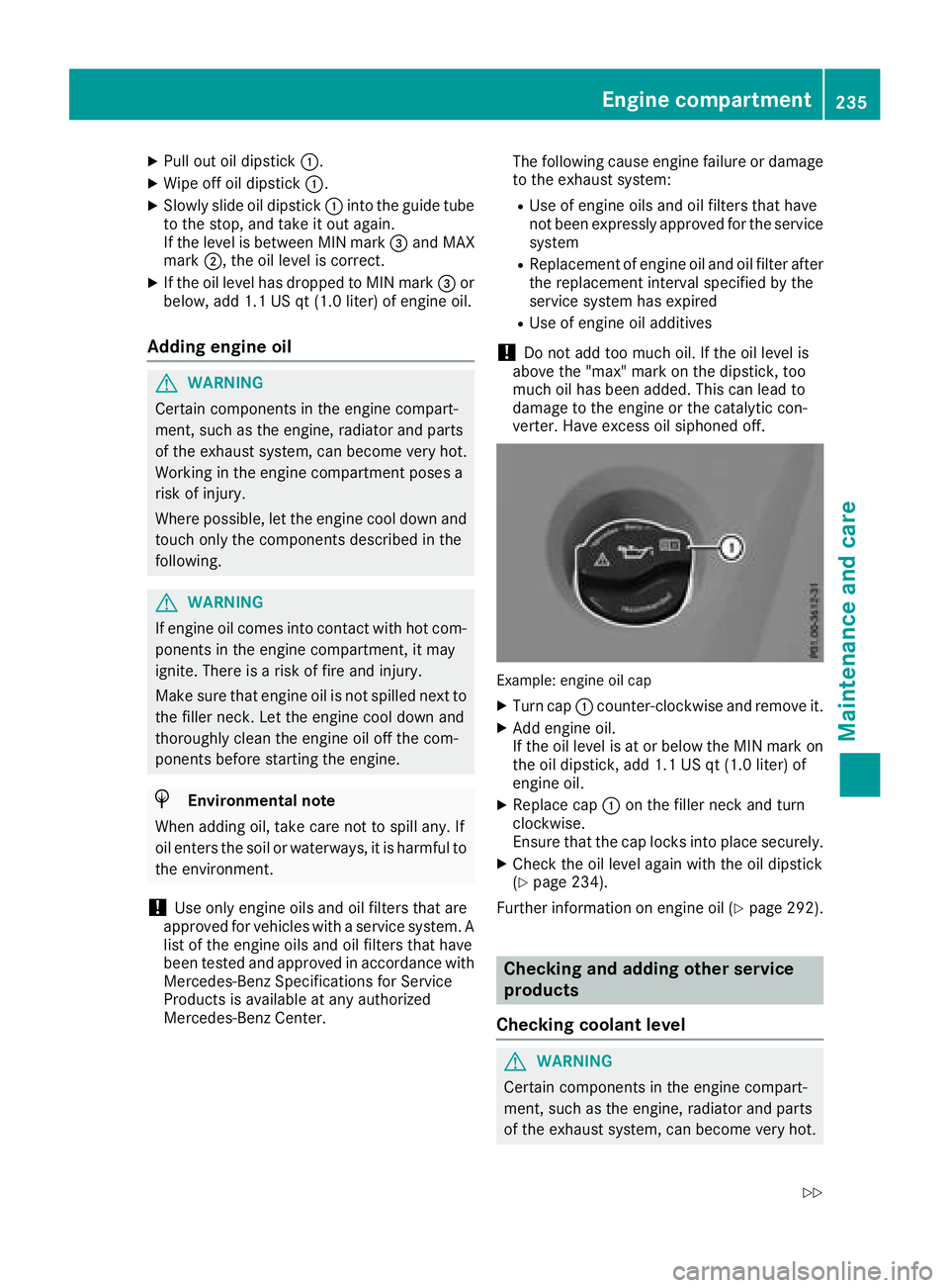
Example: engine oil cap
XTurn cap :counter-clockwise and remove it.
XAdd engine oil.
If the oil level is at or below the MIN mark on
the oil dipstick ,add 1.1 US qt (1.0 liter) of
engine oil.
XReplace cap :on the filler neck and turn
clockwise.
Ensure that the cap locks into place securely.
XCheck the oil level again with the oil dipstick
(Ypage 234).
Further information on engine oil (
Ypage 292).
Checking and adding other service
products
Checking coolant level
GWARNING
Certain components in the engine compart-
ment ,such as the engine, radiator and parts
of the exhaust system, can become very hot.
Engine compartment235
Maintenance and care
Z
Page 271 of 298
The tire pressure monitor hasayellow warning
lamp in the instrument cluster for indicating
pressure loss or amalfunction. Whether the
warning lamp flashes or lights up indicates
whether atire pressure is too low or the tire
pressure monitor is malfunctioning:
Rif the warning lamp is lit continuously, the tire
pressure on one or more tires is significantly
too low. The tire pressure monitor is not mal- functioning.
Rif the warning lamp flashes for approximately
am inute and then remains lit constantly, the
tire pressure monitor is malfunctioning.
In addition to the warning lamp, amessage
appears in the multifunction display.O bserve
the information on display messages
(
Ypage 196).
It may take up to ten minutes for amalfunction
of the tire pressure monitor to be indicated. A
malfunction will be indicated by the tire pres-
sure warning lamp flashing for approximately
one minute and then remaining lit. When the
malfunction has been rectified, the tire pressure
warning lamp goes out after afew minutes of
driving.
The tire pressure values indicated by the on-
board computer may differ from those meas-
ured at agas station with apressure gage. The
tire pressures shown by the on-board computer
refer to those measured at sea level. At high
altitudes, the tire pressure values indicated by a pressure gage are higher than those shown by
the on-board computer. In this case, do not
reduce the tire pressures.
The operation of the tire pressure monitor can
be affected by interferenc efrom radio transmit-
ting equipment (e.g. radio headphones, two-way
radios) that may be being operated in or near the vehicle.
Checking the tire pressur eelectroni-
cally
XMake sure that the SmartKey is in position 2
(Ypage 116) in the ignition lock.
XPress the =or; button on the steering
wheel to select the Serv.menu.
XPress the9or: button to select
Tire Pressure.
XPress a.
The current tire pressure of each tire is shown
in the multifunction display. If the vehicle has been parked for over
20 minutes, the
Tire pressure will be
displayed after driving afew minutesmessage appears.
After ateach-in process, the tire pressure mon-
itor automatically detect snew wheels or new
sensors. As long as aclear allocation of the tire
pressure value to the individual wheels is not
possible, the Tire
PressureMonitorActivedisplay message is shown instead of the tire
pressure display.T he tire pressures are already
being monitored.
If an emergencys pare wheel is mounted, the
system may continue to show the tire pressure
of the wheel that has been removed for afew
minutes. Be aware that the value displayed for
the position where the emergencys pare wheel
is fitted is not the same as the current tire pres-
sure of the emergencys pare wheel.
Tire pressuremonitor warning mes-
sages
The tire pressure monitor detect sapressure
loss in one or more tires:
RIf the tire pressure monitor detect sapressure
loss in one or more tires, awarning message
is shown in the multifunction display.T he yel-
low tire pressure warning lamp then lights up.
RIf the Please Correct Tire Pressuremessage appears in the multifunction display,
the tire pressure in at least one tire is too low.
The tire pressure must be corrected when the
opportunit yarises.
RIf the Check Tiresmessage appears in the
multifunction display,t he tire pressure in at
least one tire has dropped significantly. The
tires must be checked.
RIf the WarningTireMalfunctionmessage
appears in the multifunction display,t he tire
pressure in at least one tire has dropped sud-
denly. The tires must be checked.
Observe the instructions and safety notes in the
display messages in the "Tires" section
(
Ypage 196).
If the wheel positions on the vehicle are rotated,
the tire pressures may be displayed for the
wrong positions for ashort time. This is rectified
after afew minutes of driving, and the tire pres-
sures are displayed for the correctp ositions.
Tirepressure269
Wheels and tires
Z
Page 290 of 298
Information regardingtechnicald ata
i
The dat astate dh eres pecifically refers to a
vehicl ewiths tandard equipment. Consult an
authorize dMercedes-Ben zCente rfor th e
dat afor all vehicl evariants and trim levels.
Vehicle electronics
Tampering with th eenginee lectron-
ics
!
Only hav eworkc arried out on th eengine
electronics and it sassociated parts, suc has
control units, sensors, actuating component s
and connecto rleads ,ataq ualified specialist
workshop. Vehicl ecom ponent smay other -
wise wear mor equickly and th evehicle's
operating permit may be invalidated.
Installing two-way radio sand mobile
phones (RF transmitters)
GWARNIN G
The electromagneti cradiation from two-way
radios can interfere wit hthe vehicl eelectron -
ics if two-way radios are manipulated or ret -
rofitte dincorrectly. This could jeopardiz ethe
operating safet yofthevehicle. Ther eisarisk
of an accident.
You should hav eall wor kone lectrical and
electronic component scarried out at aquali-
fie ds pecialist workshop.
GWARNIN G
If you incorrectl yoperate two-way radios in
th ev ehicle, th eelectromagneti cradiation
may interfere wit hthe vehicl eelectronics ,for
exampl eif:
Rthet wo-way radi oisnotconnecte dtoan
exterio rantenna
Rthee xter iora ntenna is no tcorrectly moun-
te dorisn otlow-reflection
This could jeopardiz ethe operating safet yof
th ev ehicle. Ther eisariskofana ccident.
Havethe low-reflection exterio rantenna
installed at aqualified specialist workshop.
Always connec ttwo-way radios to th elow-
reflection exterio rantenna when operating in
th ev ehicle.
!The operating permit may be invalidated if
th ei nstruction sfor installation and use of
two-way radios are no tobserved.
In particular, th efollowin gconditi onsm ust be
complied with:
Ronly approve dwavebands may be used
Robserv ethe maximum permissible output
in these wavebands
Ronly approve dantenna position smay be
used
Excessiv elevels of electromagneti cradiation
may caus edamag etoyour healt hand th ehealt h
of others. Using an exterio rantenna takes int o
accoun tcurren tscientific discussion srelating
to th epossible healt hhazards that may result
from electromagneti cfields.
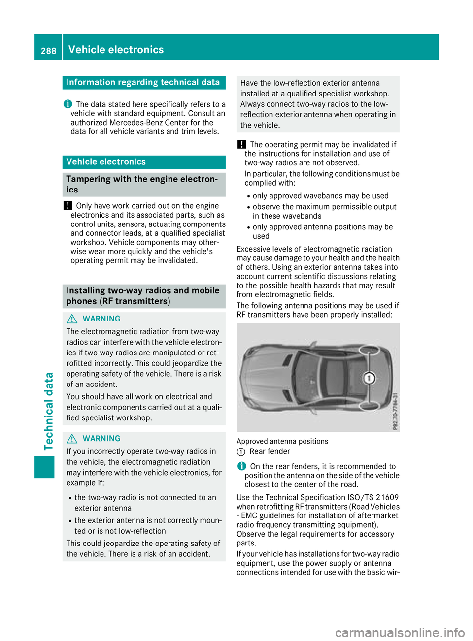
The followin gantenna position smay be used if
RF transmitters hav ebeen properly installed:
Approved antenna position s
:
Rear fender
iOn th erear fenders, it is recommended to
position th eantenna on th eside of th evehicl e
closes ttothecenter of th eroad .
Use th eTechnical Specification ISO/TS 2160 9
when retrofitting RF transmitters (Road Vehicles
-E MC guidelines for installation of aftermarket
radi ofrequency transmitting equipment) .
Observ ethe legal requirements for accessory
parts.
If your vehicl ehas installation sfor two-way radi o
equipment, use th epower suppl yorantenna
connection sintended for use wit hthe basic wir-
288Vehicle electronics
Technical data
Page 291 of 298
ing. Be sure to observe the manufacturer'sSup-
plementw hen installing.
Deviation swith respect to frequenc ybands,
maximum transmission output sorantenna
positions must be approved by Mercedes-Benz.
The maximum transmission output (PEAK) at the
base of the antenn amust not exceed the fol-
lowing values:
Frequency bandMaximum
transmission output
Short wave
3-54M Hz100 W
4mwaveband
74 -88M Hz30 W
2mwaveband
144 -174 MHz50 W
Trunked radio system/
Tetra
380 -460 MHz10 W
70 cm waveband
400 -460 MHz35 W
Mobile communications
(2G/3G/4G)10 W
The followingc an be used in the vehicle without
restrictions:
RRF transmitters with amaximum transmis-
sion output of up to 100 mW
RRF transmitters with transmitter frequencies
in the 380 -410 MHz wavebanda ndam axi-
mum transmission output of up to 2W
(trunked radio/Tetra)
RMobile phones (2G/3G/4G)
There are no restrictions when positionin gthe
antenn aonthe outside of the vehicle for the
followingw avebands:
RTrunked radio system/Tetra
R70 cm waveband
R2G/3G/4G
Identification plates
Vehicle identification plate with vehi-
cle identification number (VIN)
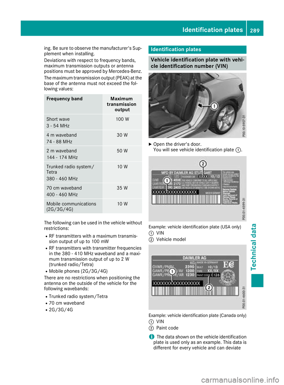
XOpen the driver's door.
You will see vehicle identification plate :.
Example: vehicle identification plate (USA only)
:
VIN
;Vehicle model
Example: vehicle identification plate (Canada only)
:
VIN
;Paint code
iThe data shown on the vehicle identification
plate is used only as an example. This data is
differentf or everyvehicle and can deviate
Identification plates289
Technicald ata
Z