2018 MERCEDES-BENZ SLC ROADSTER seats
[x] Cancel search: seatsPage 94 of 298
thenopent he driver's or front-passenger
door.
iThe exterio rmirrors do not fol doutif they
have been folde dinmanually.
Exterior mirro rpushed ou tofposition
If an exterio rmirrorh asbeen pushe doutof
position, procee dasfollows:
XVehicle swithout electricall yfolding exte-
rio rm irrors: movethe exterio rmirrori nto
the correct positio nmanually.
XVehicle swithe lect ricall yfolding exterior
mirrors: press and hol dmirror-folding button
unti lyou hear the mirrorc lick into place
(
Ypage 91).
The mirrorh ousing is engaged agai nand you
can adjus tthe exterio rmirrors as usual
(
Ypage 91).
Automati canti-glare mirrors
GWARNING
Electrolyte maye scap eift he glas sinana uto-
matic anti-glar emirror breaks. Th eelectrolyte
is harmfula nd causesirritation. It must not
come into contact with your skin, eyes ,res-
piratory organs or clothing or be swallowed.
There is ariskofi njury.
If yo ucome into contact with the electrolyte,
observe the following:
RRinse off the electrolyte fromy ours kin
immediatel ywithw ater.
RImmediately rinse the electrolyte ou tof
your eyes thoroughl ywithc lean water.
RIf the electrolyte is swallowed, immediately
rinse your mouth ou tthoroughly. Do not
induce vomiting.
RIf electrolyte come sinto contact with your
skinorh airoriss wallowed ,see km edical
attentio nimm ediately.
RImmediately change ou tofclothing which
hasc ome into contact with electrolyte.
RIf an allergi creactio noccurs, seek medical
attentio nimm ediately. The rear-view mirrora
nd the exteriormirroro n
the driver's side automaticall ygointo anti-glare
mod eift he following conditions ar emet simul-
taneously:
Rthe ignition is switched on and
Rincident light fromh eadlamps strikes the sen-
sor in the rear-view mirror
The mirrors do not go into anti-glar emodei
f
re
vers egearise ngaged or if the interio rlighting
is switched on.
Parking position fort he exterior mir-
ror on the front-passenge rside
Settin gand storin gthe parking position
Usin grevers egear
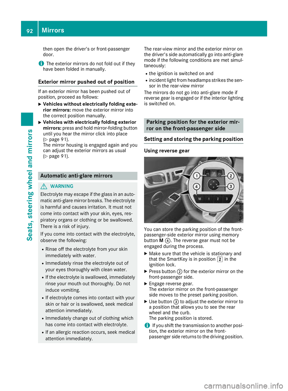
Youc an stor ethe parking positio nofthe front-
passenger-side exterio rmirroru sing memory
button M?.T he reverse gea rmustn ot be
engaged durin gthe process.
XMake sure thatt he vehicleisstationar yand
thatt he SmartKeyisinp osition 2in the
ignition lock.
XPress button ;for the exterio rmirror ont he
front-passenge rside.
XEngage revers egear.
The exterio rmirroront he front-passenger
side moves to the presetp arking position.
XUse button =to adjus tthe exterio rmirrort o
ap osit iont hata llowsyou to seet he rear
whee land the curb.
Th ep arking positio niss tored.
iIf yo ushift the transmission to anotherp osi-
tion, the exterio rmirroront he front-
passenge rsider eturns to the drivin gposit ion.
92Mirrors
Seats, steering wheel andmirrors
Page 95 of 298
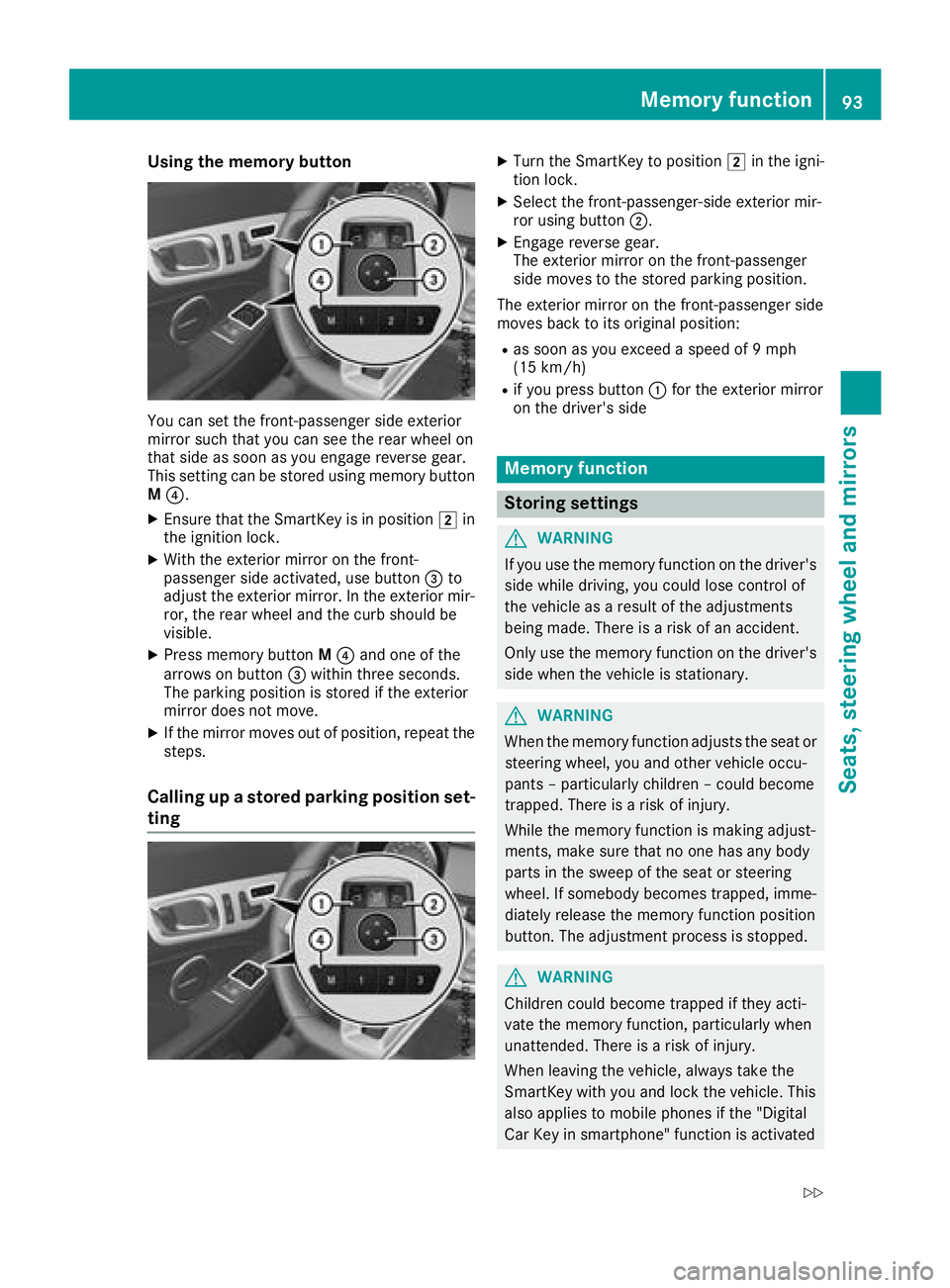
Using the memory button
You can set the front-passenger side exterior
mirror such that you can see the rear wheel on
that side as soon as you engage reverse gear.
This setting can be stored using memorybutton
M ?.
XEnsure that the SmartKey is in position 2in
the ignition lock.
XWith the exterior mirror on the front-
passenger side activated, use button =to
adjust the exterior mirror.Int he exterior mir-
ror, the rear wheel and the curb should be
visible.
XPress memoryb uttonM? and one of the
arrows on button =within three seconds.
The parkin gposition is stored if the exterior
mirror does not move.
XIf the mirror moves out of position ,repeat the
steps.
Calling up astored parking position set-
ting
XTurn the SmartKey to position 2in the igni-
tion lock.
XSelec tthe front-passenger-side exterior mir-
ror using button ;.
XEngage reverse gear.
The exterior mirror on the front-passenger
side moves to the stored parkin gposition.
The exterior mirror on the front-passenger side
moves back to its original position:
Ras soon as you exceed aspeed of 9mph
(15 km/h)
Rif you press button :for the exterior mirror
on the driver'ss ide
Memoryfunction
Storing settings
GWARNING
If you use the memoryf unction on the driver's
side while driving, you could lose contro lof
the vehicle as aresult of the adjustments
being made. There is arisk of an accident.
Only use the memoryf unction on the driver's
side when the vehicle is stationary.
GWARNING
When the memoryf unction adjuststhe seat or
steering wheel, you and other vehicle occu-
pant s–p articularly children –could become
trapped. There is arisk of injury.
While the memoryf unction is makingadjust-
ments, make sure that no one has any body
parts in the sweep of the seat or steering
wheel. If somebody becomes trapped, imme-
diately release the memoryf unction position
button. The adjustment proces sisstopped.
GWARNING
Children could become trapped if they acti-
vate the memoryf unction,particularly when
unattended. There is arisk of injury.
When leaving the vehicle, always tak ethe
SmartKey with you and lock the vehicle. This
also applies to mobile phones if the "Digital
Car Key in smartphone" function is activated
Memor yfunction93
Seats, steering wheel and mirrors
Z
Page 96 of 298
via the Mercedesmeconnect web app.Never
leave children unsupervisedint he vehicle.
The memory function can be activated at any
time, e.g. even when the SmartKey is not in the ignitio nlock.
With the memory function, you can store up to
three different settings, e.g. for three different
people.
The following settings are stored as asingle
memory preset:
Rposition of the seat, backrest and head
restraint
Rdriver'ss ide:steering wheelp osition
Rdriver'sside:position of the exterior mirrors
on the driver'sa nd front-passenge rsides
XAdjust the seat electrically (Ypag e86).
XOn the driver'ss ide,adjust the steering wheel
(Ypag e89) and the exterior mirrors
(Ypag e91).
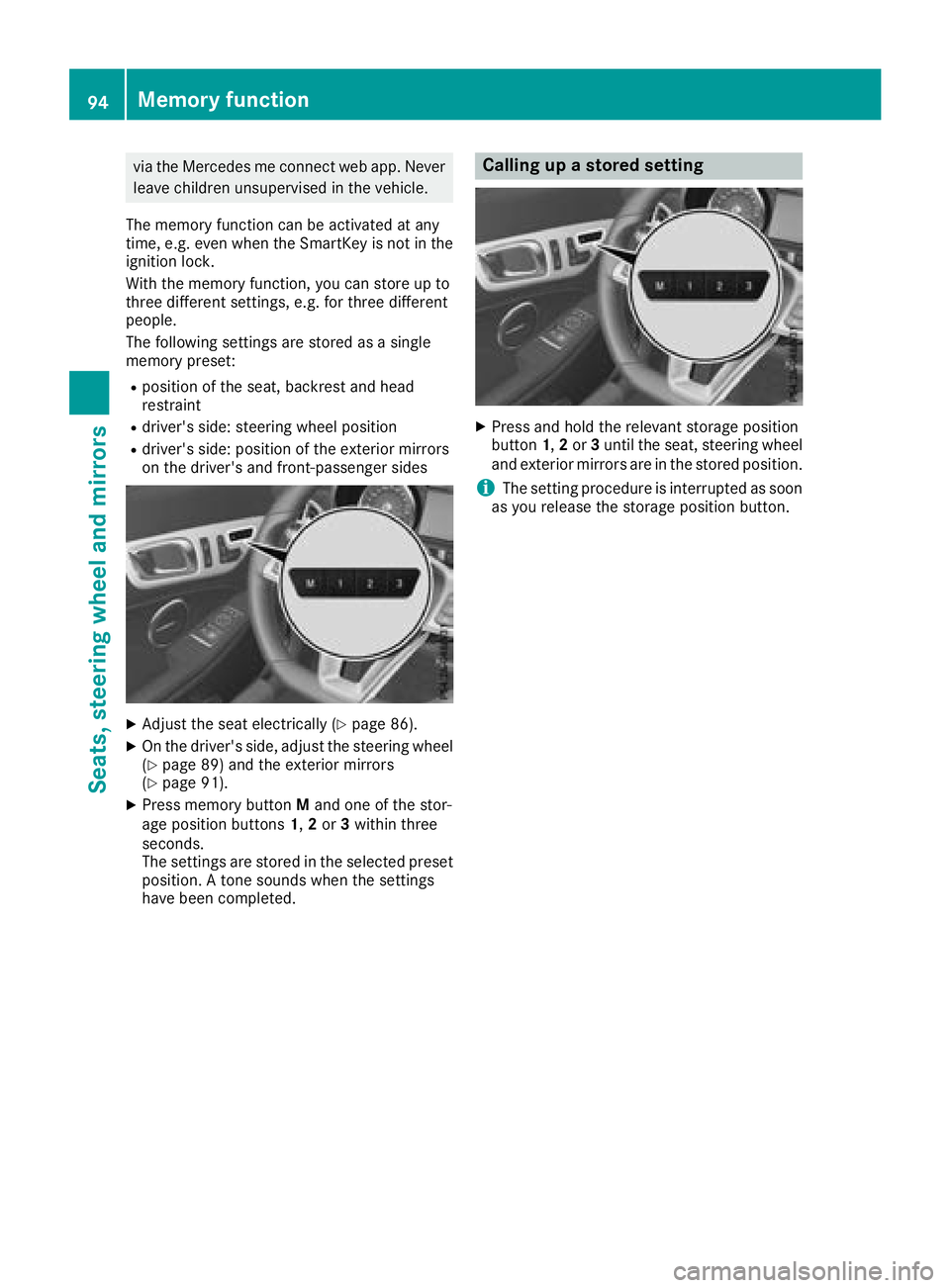
XPress memory button Mand one of the stor-
age position buttons 1,2or 3withi nthree
seconds.
The settings are stored in the selected preset
position. Atone sounds when the settings
have been completed.
Calling up astored setting
XPress and hold the relevant storage position
button 1,2or 3until the seat, steering wheel
and exterior mirrors are in the stored position.
iThe setting procedure is interrupted as soon
as you release the storage position button.
94Memory function
Seats, steering wheel and mirrors
Page 222 of 298
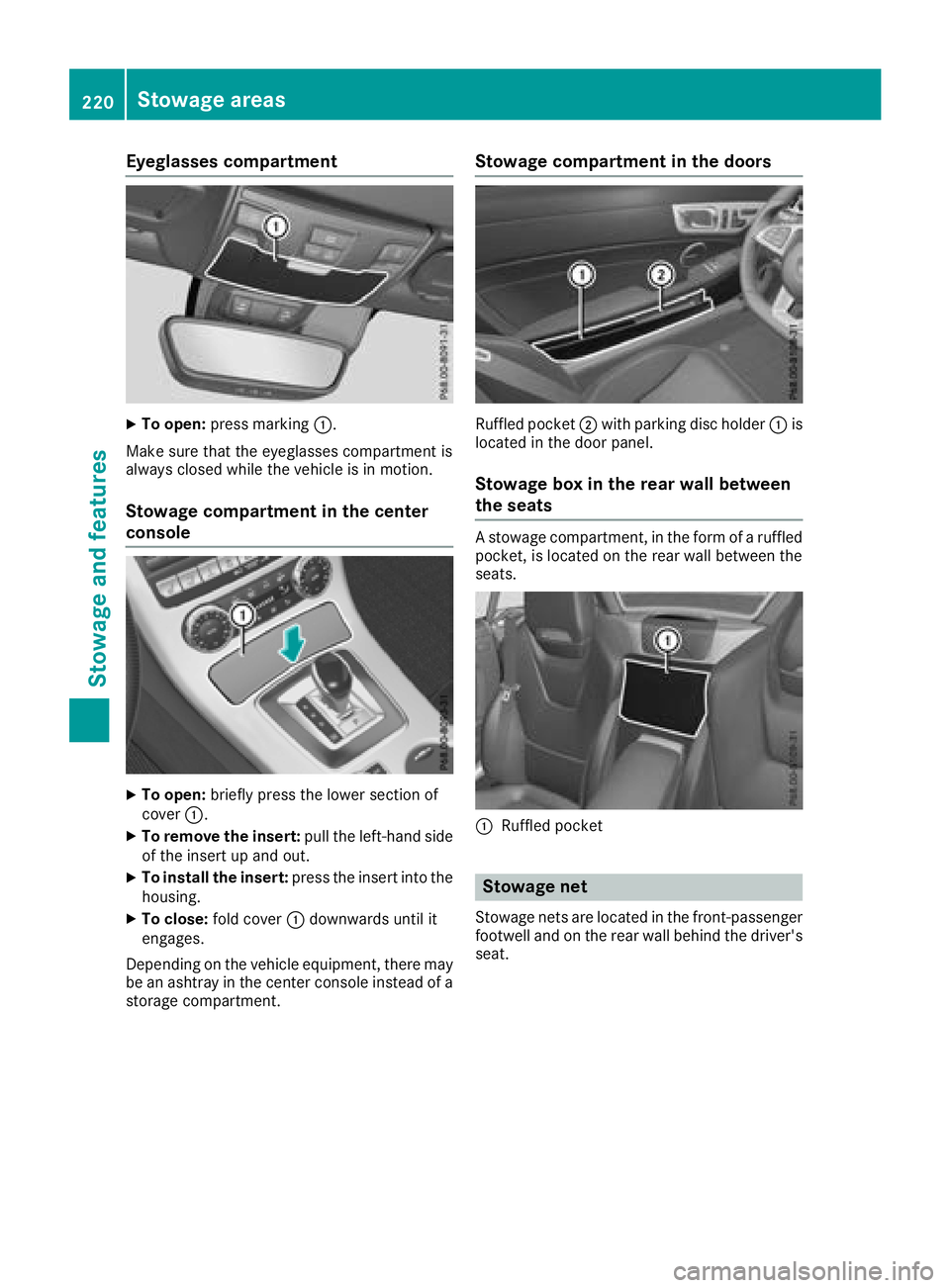
Eyeglasses compartment
XTo open:pressmarking :.
Makes ure that th eeyeglasses compartmen tis
always closed while th evehicle is in motion.
Stowage compartment in th ecenter
console
XTo open: briefly pres sthe lower sectio nof
cover :.
XTo remove th einsert: pull theleft-hand side
of th einsert up and out.
XTo install th einsert: pressthe insert int othe
housing.
XTo close: fold cover :downwards until it
engages.
Dependingont hevehicle equipment ,the re may
be an ashtray in th ecente rconsole instead of a
storag ecompartment.
Stowage compartment in th edoors
Ruffled pocket ;with parking disc holder :is
locate dinthedoor panel.
Stowage box in th erearw all between
th es eats
Astowage compartment, in th eformofar uffled
pocket, is locate dontherear wall between the
seats.
:Ruffled pocket
Stowage net
Stowage net sare locate dinthefront-passenger
footwell and on th erear wall behindt hedriver's
seat.
220Stowage areas
Stowage and features
Page 253 of 298
Battery (vehicle)
Important safety notes
Specialtool sand expert knowledg eare required
when working on the battery ,e.g.r emovala nd
installation. Yo ushoul dtherefore have al lwork
involving the battery carrie doutataq uali fied
specialist workshop.
GWARNING
Wor kcarrie doutincorrectly on the battery
can lead ,for example, to ashort circui tand
thusd amagethe vehicl eelectronics .Thisc an
lead to functio nrestrictions applying to
safety-relevant systems, e.g .the lighting sys-
tem, the ABS (anti-lock braking system )orthe
ESP
®(Electronic Stability Program). The oper-
ating safety of your vehicl emaybe restricted.
Yo uc ould lose controloft he vehicle, for
example:
Rwhen braking
Rin the event of abrupt steering maneuvers
and/or when the vehicle's speed is not
adapted to the roadc onditions
There is ariskofana ccident.
In the event of ashort circui torasimilar inci-
dent, contact aquali fied specialist workshop
immediately. Do not drive any further .You
shoul dhavea llwork involving the battery car-
rie do utataq uali fied specialist workshop.
For further informatio nabout ABS and ESP
®,
see (Ypage 57 )and (Ypage 60).
GWARNING
Electrostati cbuild -upc an lead to the creation
of sparks, which could ignite the highl yexplo-
sive gases of abattery.T here is ariskofa n
explosion.
Before handling the battery ,touch the vehicle
body to remove any existing electrostatic
build-up.
The highl yflammabl egasmixture form swhen
charging the battery as well as when jump-start-
ing. Alway
smakes uret hatn either yo unor the bat-
tery is electrostaticall ycharged. Abuild -upo f
electrostatic charge can be caused ,for exam-
ple:
Rby wearing clothing made from synthetic
fibers
Rdu etof rictionbetween clothing and seats
Rif yo upushorp ullt he battery across the car-
pe toro thersyntheti cmaterials
Rif yo uwipet he battery with acloth
GWARNING
During the charging process ,abattery produ-
ces hydrogen gas. If ashort circui toccurs or
sparks are created,t he hydrogen gascan
ignite .There is ariskofane xplosion.
RMake sure thatt he positive terminal of a
connected battery does not come into con- tact with vehicl eparts.
RNever place meta lobjects or tool sonabat-
tery.
RIt is important thaty ouobserve the descri-
be do rder of the battery terminal swhen
connecting and disconnecting abattery.
RWhe njump-starting ,makes uret hatt he
battery pole swithi de ntical polarity are
connected.
RIt is particularly important to observe the
describe dorder when connecting and dis-
connecting the jumper cables.
RNever connect or disconnect the battery
terminal swhile the engine is running.
GWARNING
Battery aci discaustic .There is ariskofi njury.
Avoidc ontact with skin, eyes or clothing. Do
not inhal eany battery gases .Donot lean over
the battery .Keepc hildren away from batter-
ies. Wash away battery aci dimmediatelyw ith
plenty of clean water and see kmedica latten-
tion.
HEnvironmental note
Batterie scontain pollu-
tants .Itisi llegalto dispose
of them with the household
Battery (vehicle)251
Breakdo wn assis tance
Z
Page 266 of 298
Tire and LoadingInfor matio nplacard
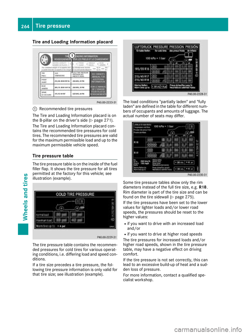
:Recommended tire pressures
The Tire and Loading Informatio nplacard is on
the B-pillar on the driver's side (
Ypage 271).
The Tire and Loading Informatio nplacard con-
tains the recommende dtire pressures for cold
tires. The recommende dtire pressures ar evalid
for the maximum permissibl eloa da nd up to the
maximum permissibl evehicl espeed.
Tire pressure table
The tire pressure table is on the insid eofthe fuel
fille rflap. It shows the tire pressure for al ltires
permitted at the factory for thisv ehicle; see
illustratio n(example).
The tire pressure table contains the recommen-
de dp ressures for col dtiresfor various operat-
ing conditions, i.e .differin gloa da nd spee dcon-
ditions.
If at ire size precedes atire pressure, the fol-
lowing tire pressure informatio niso nlyv alid for
thatt ire size; see illustratio n(example).
The load conditions "partiall yladen "and "fully
laden" ar edefine dint he table for different num-
bers of occupants and amounts of luggage.T he
actual numbe rofseats mayd iffer.
Some tire pressure table sshowo nlyt he rim
diameters instea dofthe full tire size, e.g. R18.
Ri md iame terisp artoft he tire size and can be
found on the tire sidewall (
Ypage 275).
If the tire pressures have been set to the lower
values for lighte rloads and/or lowe rroad
speeds ,the pressures shoul dbereset to the
highe rvalues :
Rif youwanttod rive with an increased load
and/or
Rif yo uwanttod rive at highe rroa ds peeds
The tire pressures for increased load sand/or
highe rroa ds peeds, shown in the tire pressure
table ,mayhave anegative effect on driving
comfort.
If the tire pressure is not set correctly, thisc an
lead to an excessive build-u pofheata nd asud-
de nlossofp ressure.
For mor einformation, contact aquali fied spe-
cialist workshop.
264Tire pressure
Wheel sand tires
Page 274 of 298
Maximum permissible gross vehicle
weight rating
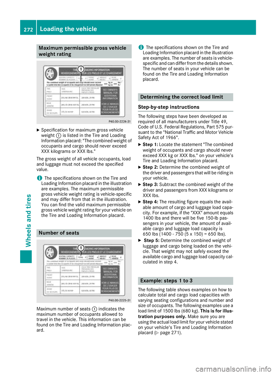
XSpecification for maximumgross vehicle
weight :is listed in the Tire and Loading
Informatio nplacard: "The combined weight of
occupants and cargo should never exceed
XXX kilograms or XXX lbs."
The gross weight of all vehicleo ccupants, load
and luggage must not exceed the specified
value.
iThe specifications shownont he Tire and
Loading Informatio nplacard in the illustration
are examples. The maximu mpermissible
gross vehiclew eight rating is vehicle-specific
and may differf rom that in the illustration.
You can find the vali dmaximu mpermissible
gross vehiclew eight rating for you rvehicleo n
the Tire and Loading Informatio nplacard.
Number of seats
Maximu mnumber of seats :indicates the
maximu mnumber of occupants allowedt o
travel in the vehicle. This information can be
found on the Tire and Loading Informatio nplac-
ard.
iThe specifications shownont he Tire and
Loading Informatio nplacard in the illustration
are examples. The number of seats is vehicle-
specific and can differf rom the details shown.
The number of seats in you rvehiclec an be
found on the Tire and Loading Information
placard.
Determiningt he correct load limit
Step-by-ste pinstructions
The following steps have been developed as
required of all manufacturers under Title 49,
Cod eofU .S. FederalR egulations, Part 575 pur-
suant to the "National Traffi cand Motor Vehicle
Safety Act of 1966".
XStep 1: Locate the statement "The combined
weight of occupants and cargo should never
exceed XXX kg or XXX lbs." on you rvehicle’s
Tire and Loading Informatio nplacard.
XStep 2: Determine the combined weight of
the drivera nd passengers that wil lberiding in
you rvehicle.
XStep 3: Subtract the combined weight of the
drivera nd passengers from XXX kilograms or
XXX lbs.
XStep 4: The resulting figure equals the avail-
abl eamount of cargo and luggage loadc apa-
city. For example, if the "XXX "amount equals
1400 lbs and there wil lbefive 150-lb pas-
sengers in you rvehicle, the amount of avail-
abl ecargo and luggage loadc apacity is
650 lbs (1400 -750 (5 x150) = 650 lbs).
XStep 5: Determine the combined weight of
luggage and cargo being loaded on the vehi-
cle. That weight may not safel yexceed the
available cargo and luggage loadc apacity cal-
culated in step 4.
Example:s teps1to3
The following table showse xamples on how to
calculate total and cargo loadc apacities with
varying seating configurations and number and
size of occupants. The following examples use a
loadl imitof1 500 lbs (680 kg). This is for illus-
tration purposes only. Make sure you are
using the actua lloadl imitf or you rvehicles tated
on you rvehicle's Tire and Loading Information
placard (
Ypage2 71).
272Loading the vehicle
Wheels and tires
Page 282 of 298
Weight of optional extras
The combined weight of those optionalextras
that weigh more than the replaced standard
parts and more than 2.3 kg (5 lbs).T hese
optionale xtras, such as high-performance
brakes ,levelc ontrol, aroof rack or ahigh-per-
formance battery,a re not included in the curb
weight and the weight of the accessories.
TIN (Tire Identification Number)
This is aunique identifier which can be use dby
at ire manufacturer to identify tires, for example
for aproduct recall, and thus identify the pur-
chasers. The TIN is made up of the manufactur-
er's identity code, tire size, tire type code and
the manufacturing date.
Load bearin gindex
The loadb earing index (also loadi ndex) isacode
that contains the maximu mloadb earing capa-
city of atire.
Traction
Tractio nisthe result of friction between the tires
and the road surface.
Treadwear indicators
Narrow bars (tread wearb ars)that are distrib-
uted over the tire tread. If the tire tread is level
with the bars ,the wearl imitofá in (1.6 mm)
has been reached.
Occupant distribution
The distribution of occupants in avehicleatt heir
designated seating positions.
Total load limit
Nominall oadand luggagel oadplus68kg
(150 lbs) multiplied by the number of seats in
the vehicle.
Changing awheel
Flat tire
The "Breakdown assistance" section
(Ypage2 46) contains information and notes on
how to dealw ithaflat tire. Informatio nondriv-
ing with MOExtended tires in the event of aflat
tire can be found under "MOExtended tires (tires
with run-fla tcharacteristics" (
Ypage2 47).
Rotating the wheels
GWARNING
Interchanging the front and rear wheels may
severely impair the driving characteristics if
the wheels or tires have different dimensions. The wheelb rakes or suspension components
may als obedamaged. There is arisk of acci-
dent.
Rotate front and rear wheels only if the wheels and tires are of the same dimensions.
!On vehicles equipped with atire pressure
monitor, electronic components are located
in the wheel.
Tire-mounting tools should not be use dnear
the valve .This coul ddamage the electronic
components.
Only have tires changed at aqualified spe-
cialist workshop.
Always pay attention to the instructions and
safety notes when changing awheel
(
Ypage2 81).
The wearp atterns on the front and rear tires
differ, depending on the operating conditions.
Rotate the wheels before aclearw earp attern
has formed on the tires. Front tires typically
wearm ore on the shoulders and the rear tires in
the center.
On vehicles that have the same size front and
rear wheels, you can rotate the wheels accord-
ing to the interval sinthe tire manufacturer's
warranty book in you rvehicled ocuments. If no
warranty book is available,t he tires should be
rotated every 3,000 to 6,000 mile s(5,000 to
10,000 km) .Depending on tire wear, this may
be required earlier. Do not change the direction
of wheelr otation.
Clean the contact surfaces of the wheela nd the
brake disc thoroughly every time awhee lisr ota-
ted. Check the tire pressure and, if necessary,
restart the tire pressure loss warning system or
the tire pressure monitor.
Directio nofrotation
Tires with aspecified direction of rotation have
additionalb enefits, e.g. if there is arisk of hydro-
planing. These advantages can only be gained if
the tires are installed corresponding to the
direction of rotation.
280Changing awheel
Wheels and tires